
This page describes my efforts restoring a Heathkit ET-3400 microprocessor trainer along with a similar model, a Heathkit ET-3400A. This was part of the Retrochallenge 2011 Winter Warmup that occurred from Jan 1, 2011 to Jan 31, 2011. The Retrochallenges are designed to get retrocomputing enthusiasts to actually spend time doing what they like to do: mess about with old computers.
My project was one of three winners. One winner was Paleoferrosaurus who did a nifty project stabilizing the video output from a Apple II so that it could be recorded properly on high-end video equipment. (I stole a bit of his code for my final demo.) The other winner was Aliennerd who created a new inform-based text adventure game based on the film "Silent Running." Aliennerd's game was demonstrated to be playable on at least two of the other constestant's text adventure runtime environments. Several of the entries were really quite cool and I encourage you to check out the entire array of candidates. Visit the Retrochallenge 2011 Winter Warmup page to see the other projects.
Here are some of the highlights of my project during the month-long challenge:
It turns out that I'm not actually finished messing around with these two boards. I have started a new web page for my continuing antics with the ET-3400 and ET-3400A.
While the challenge was occurring, status updates were in reverse order with newer entries at the top. However, now that the challenge is over, I have put them in chronological order so you can read from start to finish, if that's the sort of thing you like to do.
Click on any picture to see a higher resolution version.
I had been considering entering the RetroChallenge 2011 Winter Warmup "contest" for a while, but there didn't seem to be any activity around it getting organized. Then at the last minute, a volunteer (urbancamo) put it together. I've decided to commit and have sent in my entry. My goal is fairly simple:
I'm going to fix up my Heathkit ET-3400 and ET-3400A microprocessor trainers.
The contest runs from Jan 1, 2011 through Jan 31, 2011. I'll post more info on this project once the contest begins.
Okay, we're off and running. This website is still pretty bare-bones. Click on a picture for a higher-rez version of it.
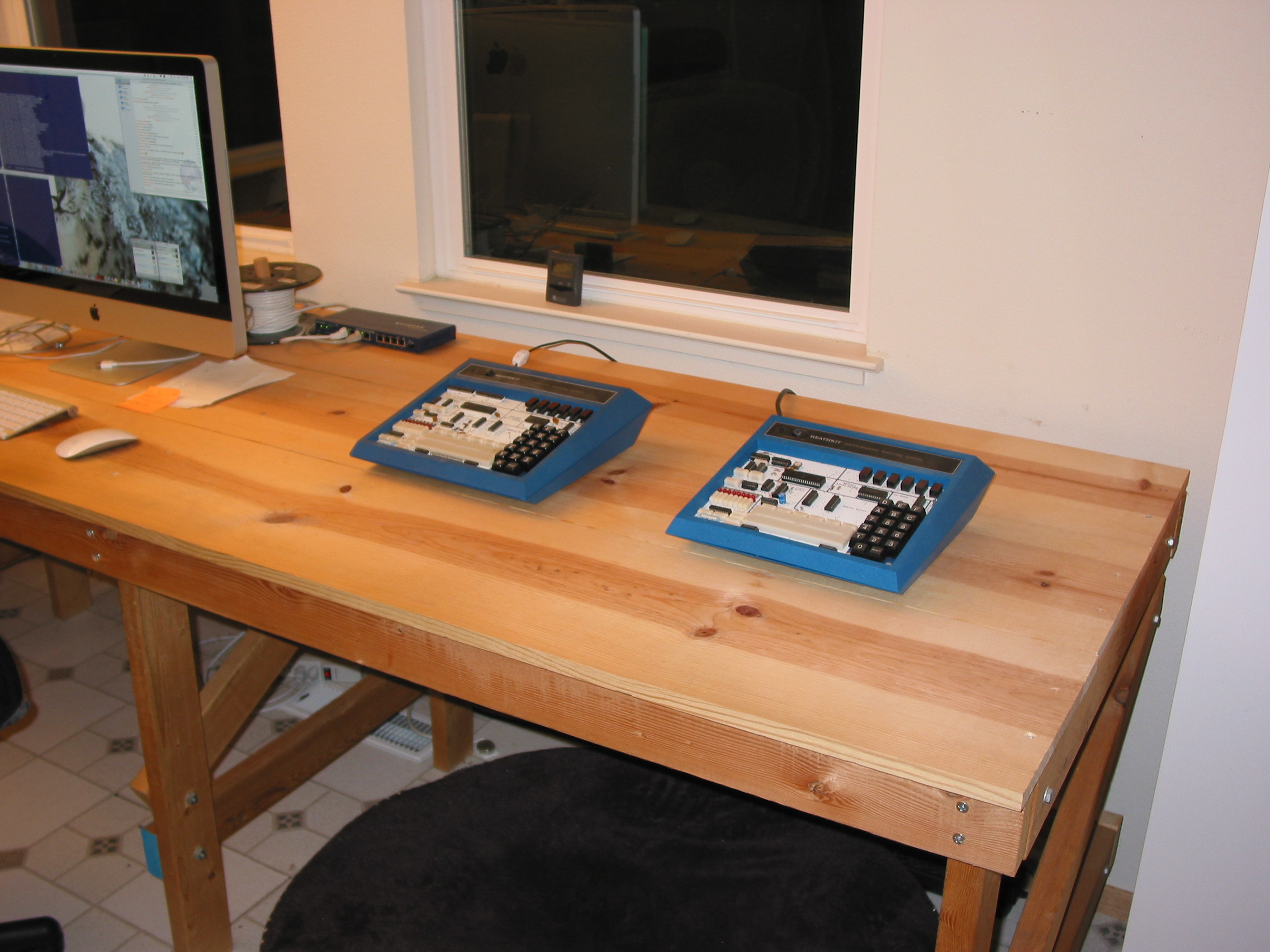
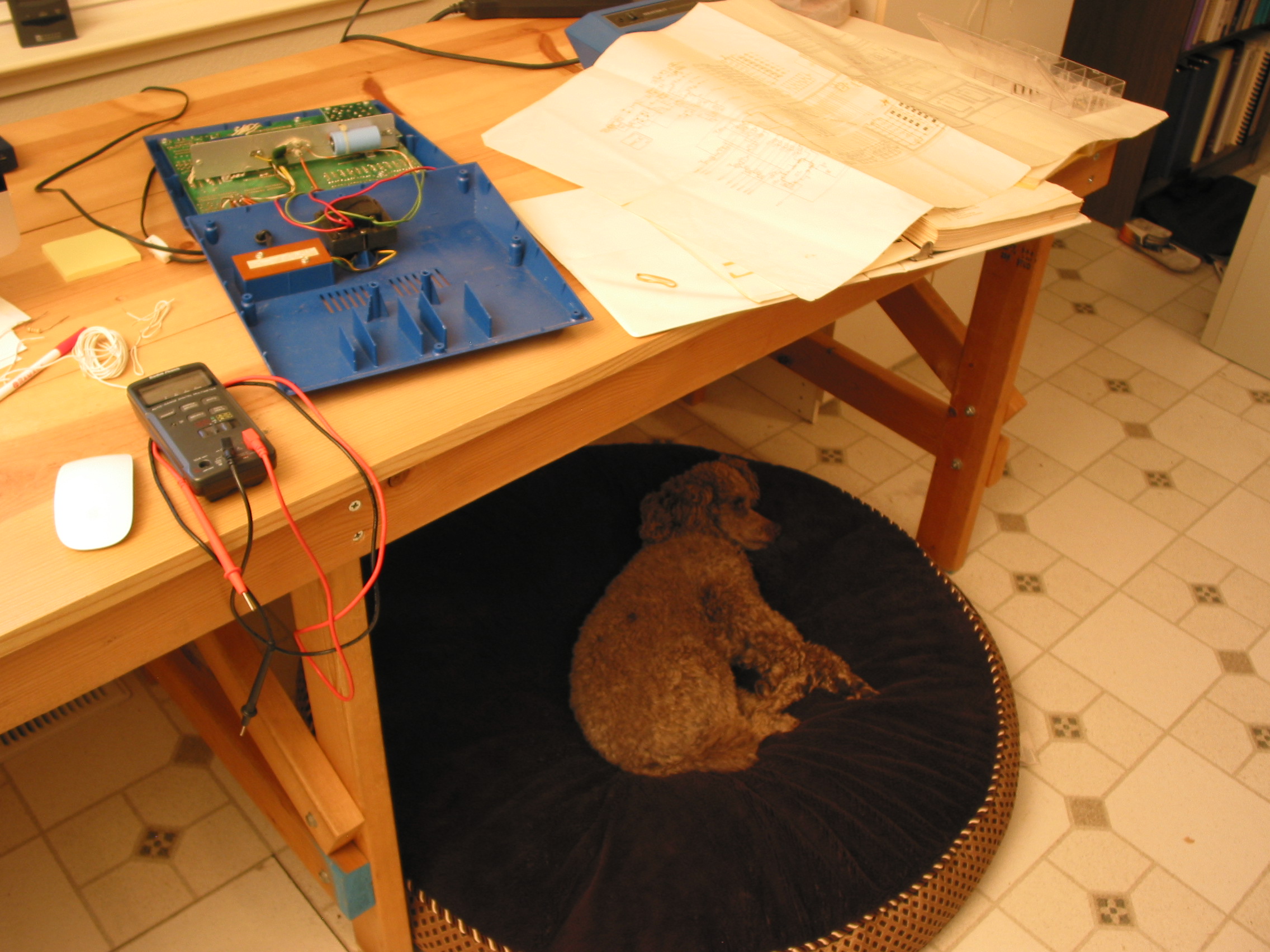
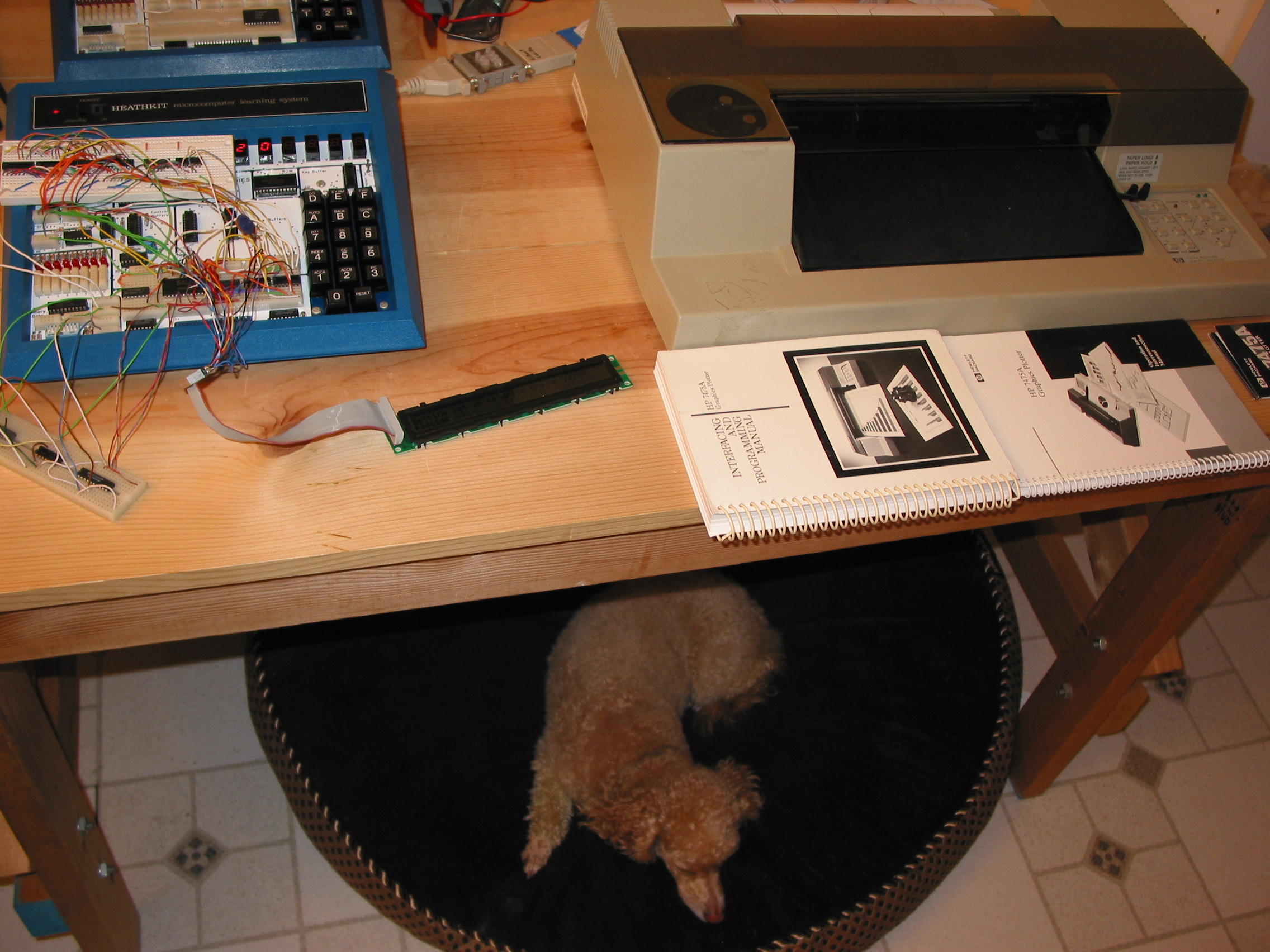
The first thing I needed to do was clean up some workspace. Here's a "before" shot:
Quick list of what you see: phone, HP-41CX, 23" Cinema Display, 27" iMac (quad-i7 2.8Ghz), ipod touch, eeepc, RLX blade server with several blades in it, a vintage ISA video card, ethernet cables, dog bed. The RLX box is practically retro now, vintage is 2001 or so. It's identical to the one at the colo which is hosting my website and other stuff and I need to do a remote upgrade. It's going to be somewhat tricky so I'm using this one as a staging/test box. (That project is going to have to go on hold for a bit during the winter warmup.) If you look closely, there's a Jelly Belly jelly-bean near the wire cutters. Just thought you should know.
After shot:
Much cleaner!
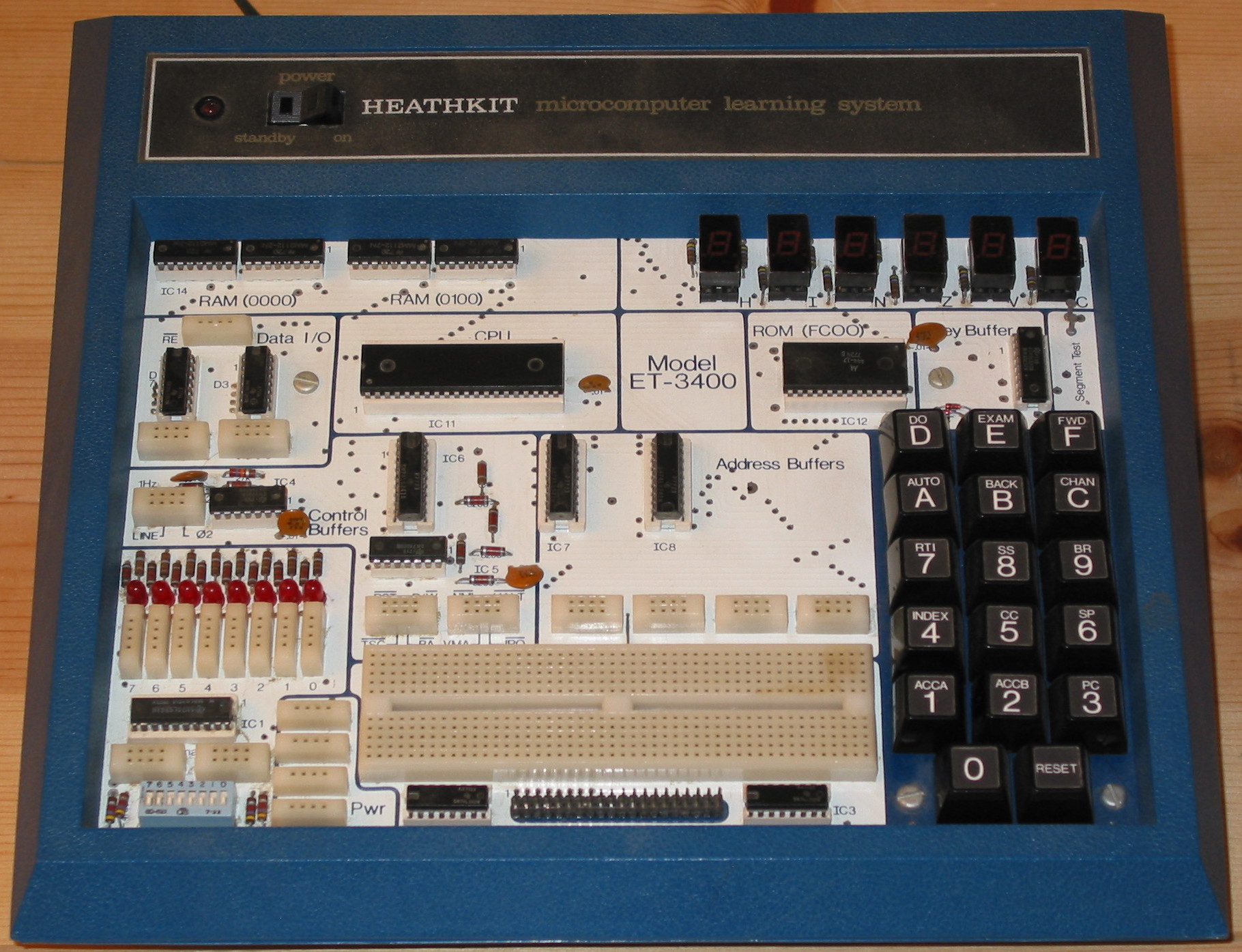
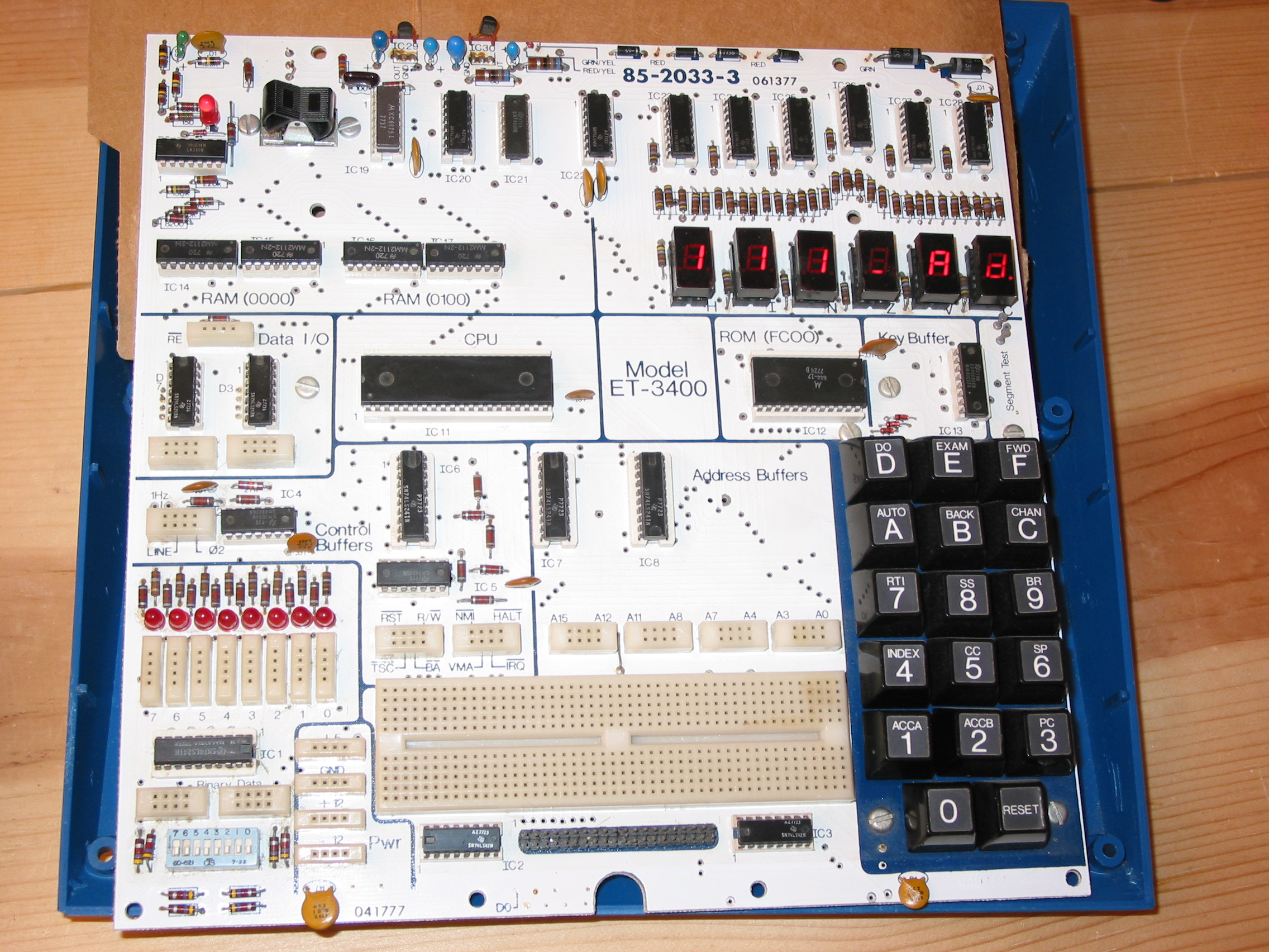
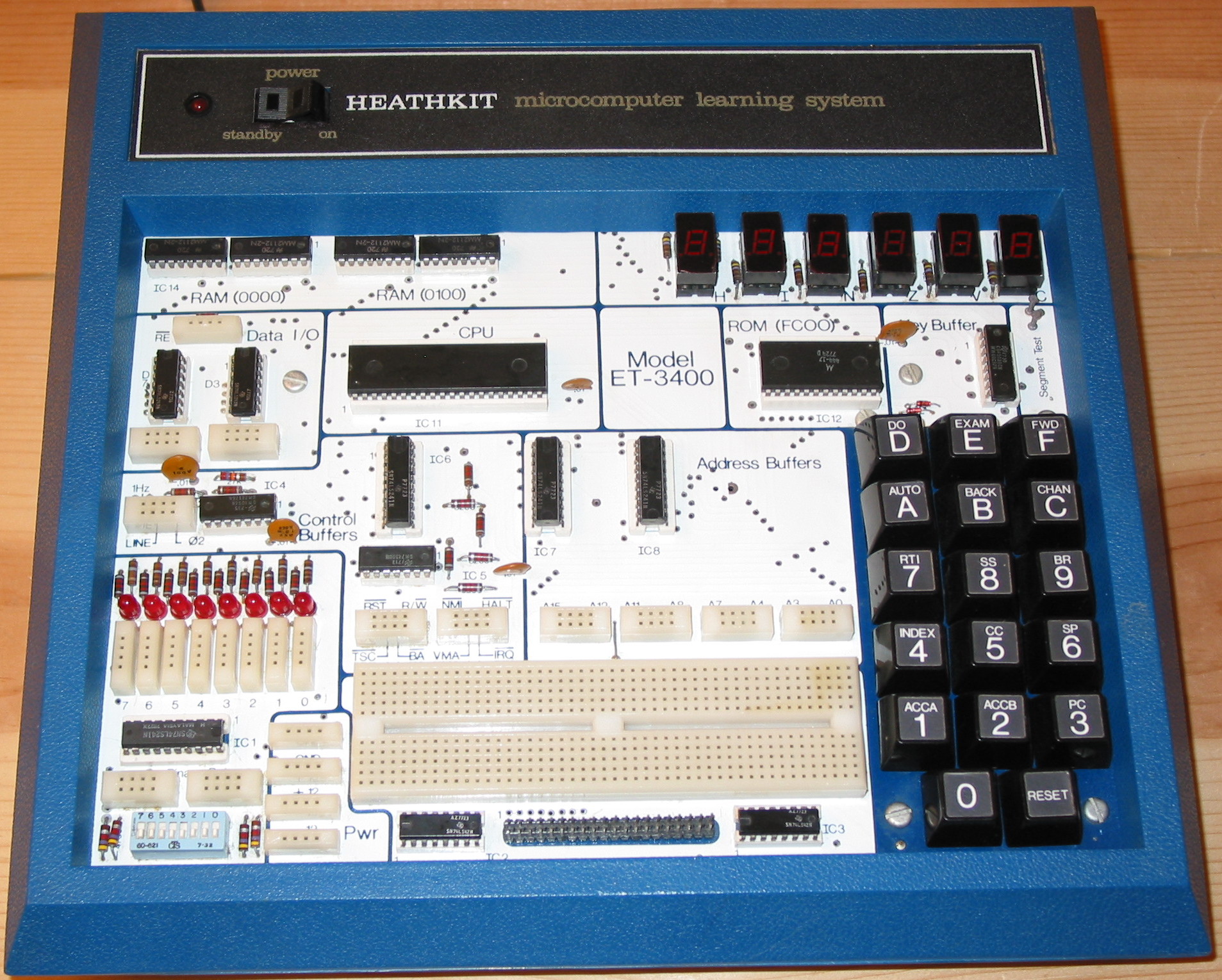
Closeup of the ET-3400:
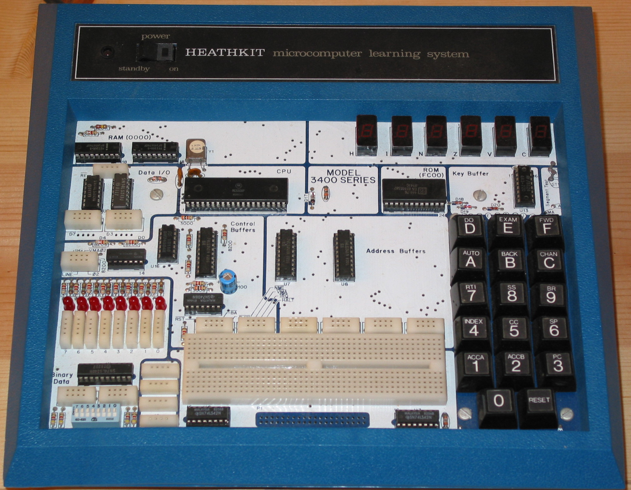
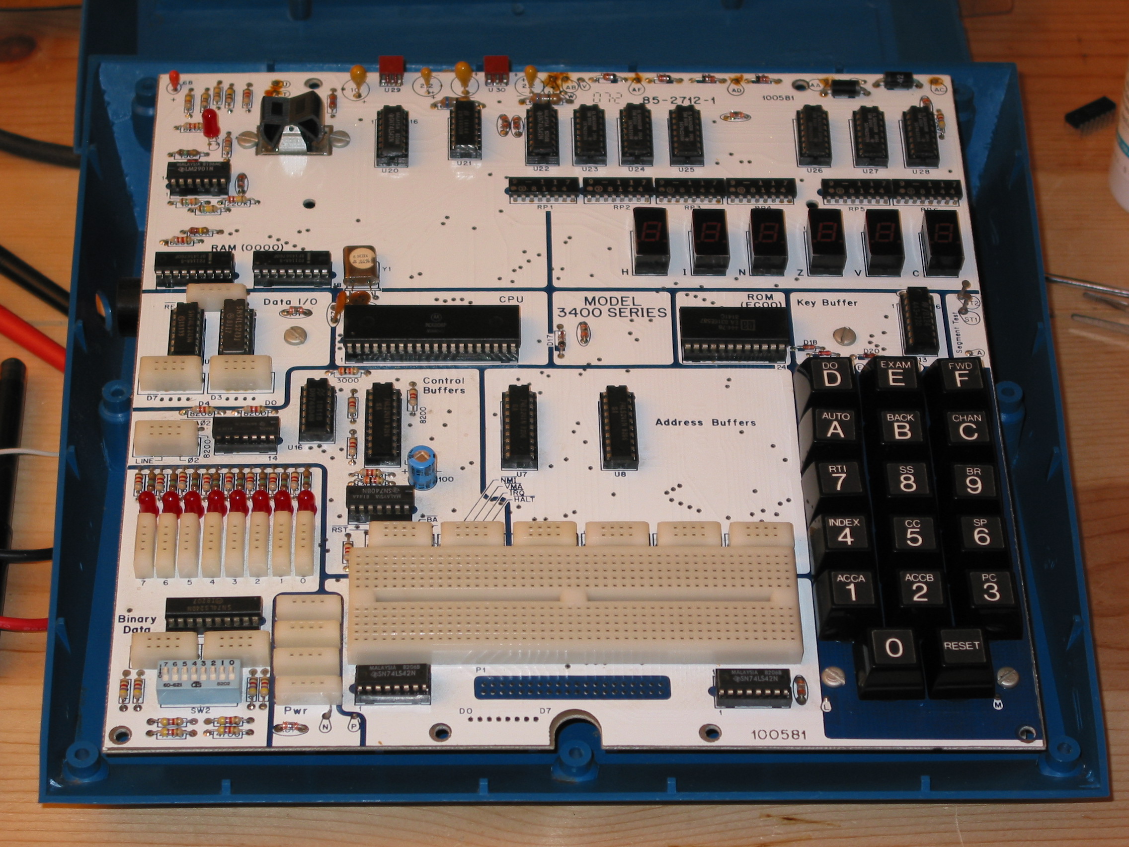
Closeup of the ET-3400A:
I'm going to start with the ET-3400. I am the original owner. My older brother and I purchased the kit in November 1977. I was 13 and he was 18. He must have been back at home from first year of college for Thanksgiving. I had plenty of experience building Heathkits at that point, so I put it together. Our dad worked for TWA and that year I travelled across the country several times with it in my carryon luggage so that I could show my bro what I had learned and fun little programs we could do on it. I definitely got more out of the ET-3400 than he did, as he had quite a bit of experience with PDP-11s and some other microprocessors already. Heathkit also had a course that went with it, the EE-3401 Individual Learning Program in Microprocessors. I went through the lessons and exercises religiously.
The ET-3400 is a small computer based around the Motorola 6800 8-bit CPU. It has 512 bytes of RAM, 1024 bytes of ROM with a simple monitor program in it, 6 seven-segment LED displays, and a hex keypad. However, the really cool things is that enough of the CPU's address, data, and control lines are exposed and there's a prototyping block available. There are 8 convenient LEDs that you can light up for whatever you want, and an 8-position dip switch for setting some other inputs. It was amazingly simple to add circuitry to the computer to try out interfacing to some new gizmo.
Many, many years ago, I was noodling around with the ET-3400 and I noticed that the "1Hz" output wasn't operating properly. This doesn't affect the operation of the computer any. It's just a signal that's provided for convenience. It's not even really 1 Hz. It's the output of a RC op-amp circuit that's "close" to 1 Hz. I remember way back that doing any serious timing with it was a mistake. For serious timing, it was better to use the 60hz signal which was based on the AC line frequency. Anyway, I've just checked by attaching a wire from the 1Hz signal to one of the handy LED inputs, and sure enough, this is still inop.
More recently, I took the unit out of storage and I tried playing with it. Unfortunately, the "1" key doesn't seem to work properly anymore. It seems like it's just not making contact. This is a show-stopper, because that's needed to change the A accumulator if you're playing with ROM monitor, and it's also needed to enter in any value that has a 1 in it. Since all input is in machine language, you just can't get very far before you need to type a "1".
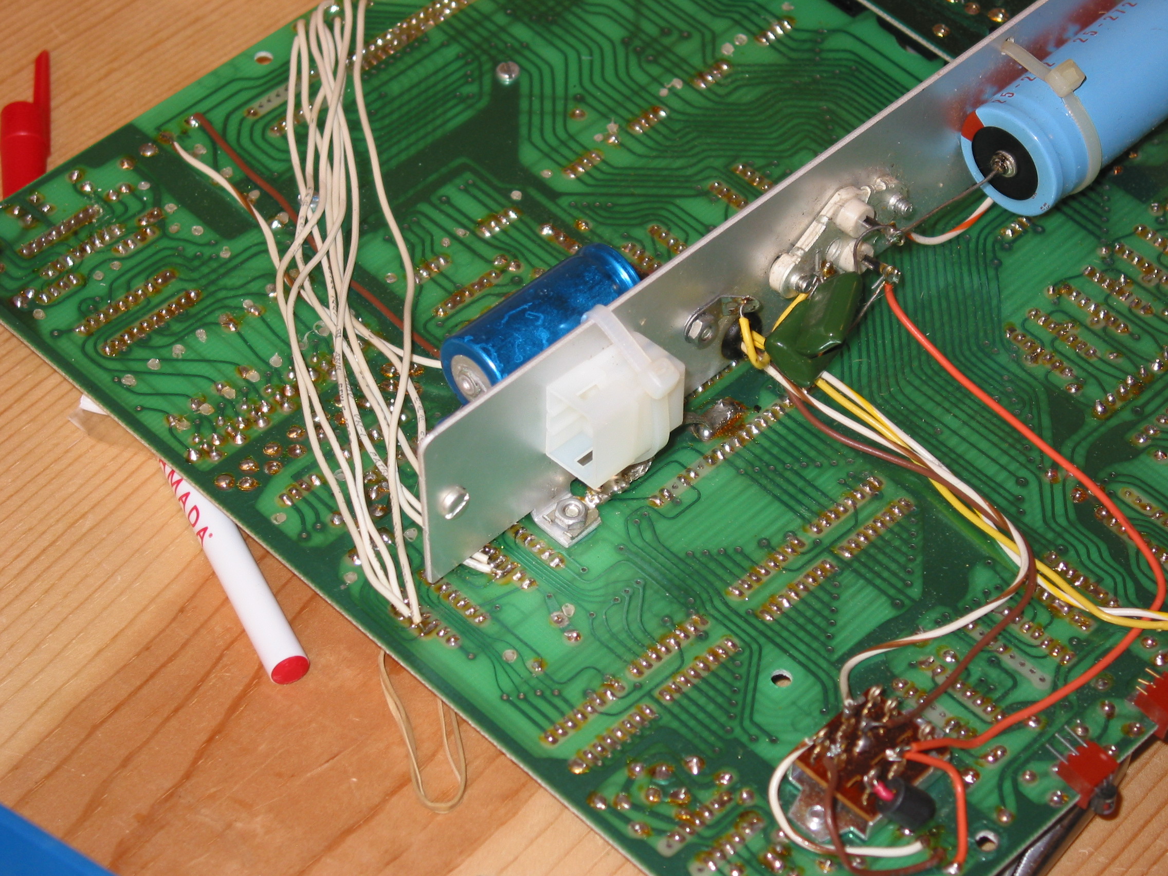
Another problem is that when you open up the device, the power-supply's transformer is on the bottom case, and the main circuit board is on the top case. I've had this thing open so many times over the years that one of the wires on the transformer keeps breaking. Several times I've had to reattach it to the circuit board, each time it gets a bit shorter, making the problem worse. As you can see from this picture, it's broken again:

Note the fine soldering. It looks like it was done by a 13-year-old!
Looking at the schematic, this is part of the 12V section of the power supply. It doesn't affect the computer operation, because 12V isn't used anywhere. Like the 1Hz signal, these +12V/-12V supplies are provided as a convenience for the circuit experimentor. They're very handy if you're doing voltage conversions for serial ports (this was all before the MAX-232 type serial interfaces) or interfacing to some of those really old TI EPROMS.
I've checked the 12V and -12V external supplies and found something pretty amazing. Even with this broken red wire, I'm still getting a pretty decent 12V and -12V supply. It's a standard full-wave bridge, but 1/2 of the input it gone. I expect there's a bit of a ripple in the outputs, but I haven't hooked up a scope to them. The +12V supply is showing 12.11 VDC and .011 VAC. The -12V supply is showing -11.88 VDC and .087 VAC. Both w/ 1 Kohm load. We'll see what these values are once the red wire is reattached.
For the ET-3400, I want to do the following things:
The ET-3400's main circuit board is attached to the top half of the plastic shell. Many of the components are visible, but some are hidden behind the upper part of the shell (behind the black label with the power switch, etc.). The IC at the heart of the 1Hz signal is hidden up there.
I detached the board from the top shell and looked for IC18, the quad comparator that uses one of its comparators in the 1Hz circuit. (Oops, not an op amp that I had remembered in my earlier post, but close.)
This is what I find:
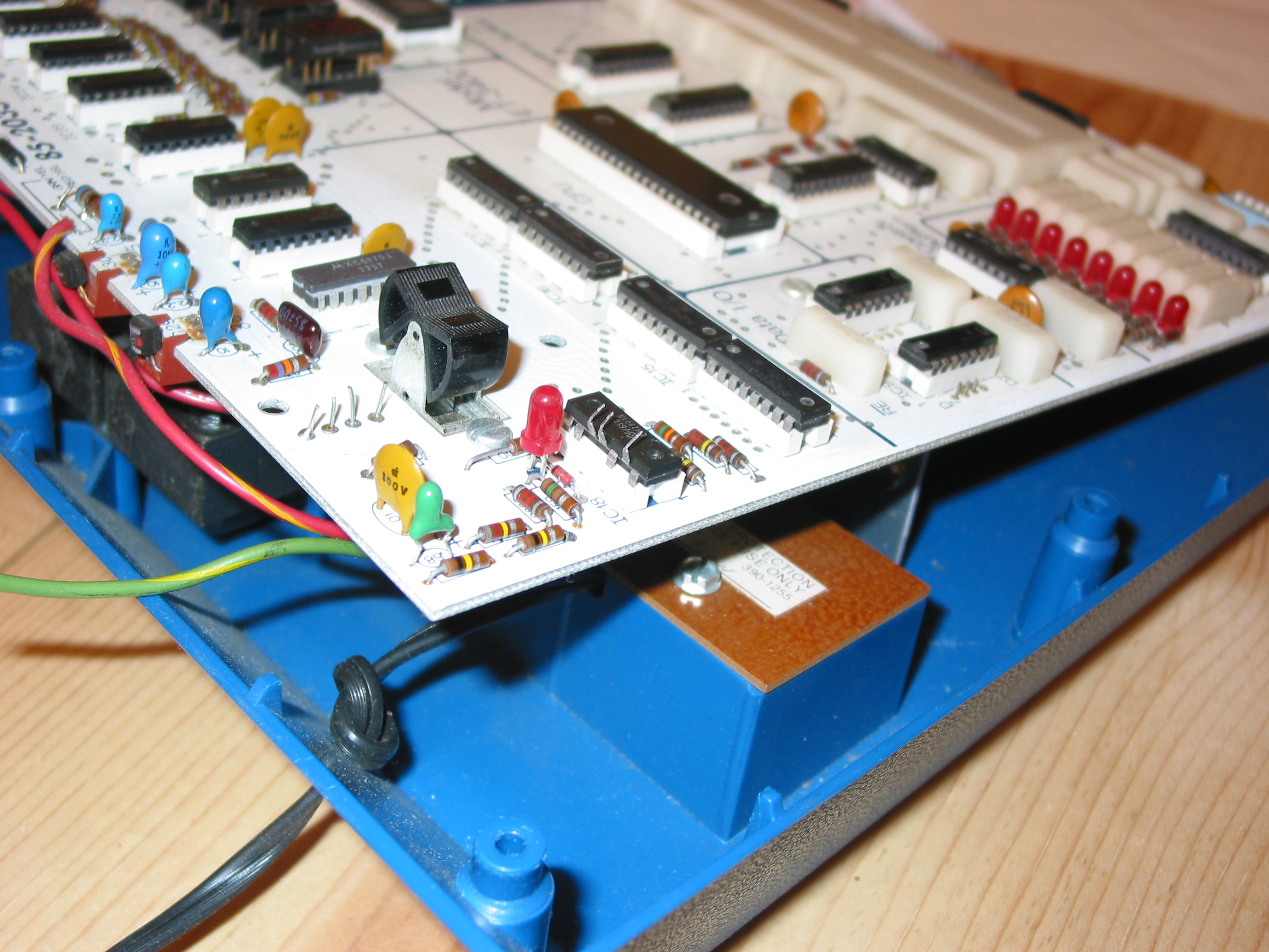
I have no idea why those pins are bent up like that. I have absolutely no recollection of doing it but it must have been me. I can think of two scenarios. Something is wrong with the quad comparator, and for some reason taking that single unit out of the circuit allows the other one to function properly. (Two of the comparators aren't used.) OR, more likely, I was messing around with RC circuits trying to get the signal closer to 1Hz. The part is a Nat Semi LM2901N. It should be a simple matter of extracting it, restoring the pins to their regular positions, and trying it out.
And while detaching the top shell, another wire from the transformer to the circuit board broke off. This time the center tap for the 5V supply. Until I get that reattached, I won't be trying out any sort of 1Hz or "1" key fixes. These tranformer wires are getting out of hand. I'm definitely going to install some sort of connector for them.
I live in a somewhat rural town, and there's not a whole lot of local choices for electronics parts. However, I did take a look in the local Radio Shack. I picked up a LM339 quad comparator and a male/female set of molex-style 6-pin power connectors. The LM339 should be a good enough replacement for the LM2901N, just in case it actually is faulty. The power connectors are going on the transformer outputs.
That's all for today. Enjoy this snapshot of my faithful assistant taking a break:
Today was my first day back at the day job this new year, plus my S.O.'s birthday. There was no time to do retrocomputing and restoration.
Since this "blog" doesn't use regular blogging software, there's no ability to leave comments. It's not that I don't want to hear from you, I just don't want to run blogging software. Therefore, I have created a special email address where you can reach me and if you'd like I'll post your comments. If you do write, be sure to specify if you want your comment posted or not. The address is rc2011ww@gc.org. Since this is out in the open, it will get harvested and get tons of spam eventually. Therefore, I'll disable it at the end of the winter warmup. After that, I can be contacted in a bunch of other ways. (It's not difficult to find out a valid email address for me. You could do a whois on me, or there's even a puzzle elsewhere on this website to find one.)
I made progress today. I'm working on the problem of the transformer wires connecting to the circuit board always breaking. I found a pretty good place to attach a molex connector on the circuit board of the ET-3400. Actually, it's the only part of the machine that could be considered a chassis. I soldered the ends of the wires on the transformer to the pins. I also soldered the pins to wires to go to the connecter on the chassis, but that side isn't done yet -- I still need to connect those wires to the circuit board itself.
Here's where the power connecter will go on the chassis:
Right now, it's attached by a zip-tie. It slides around a bit, so I may use an adhesive as well.
Inserting some pins into the connector on the transformer side:
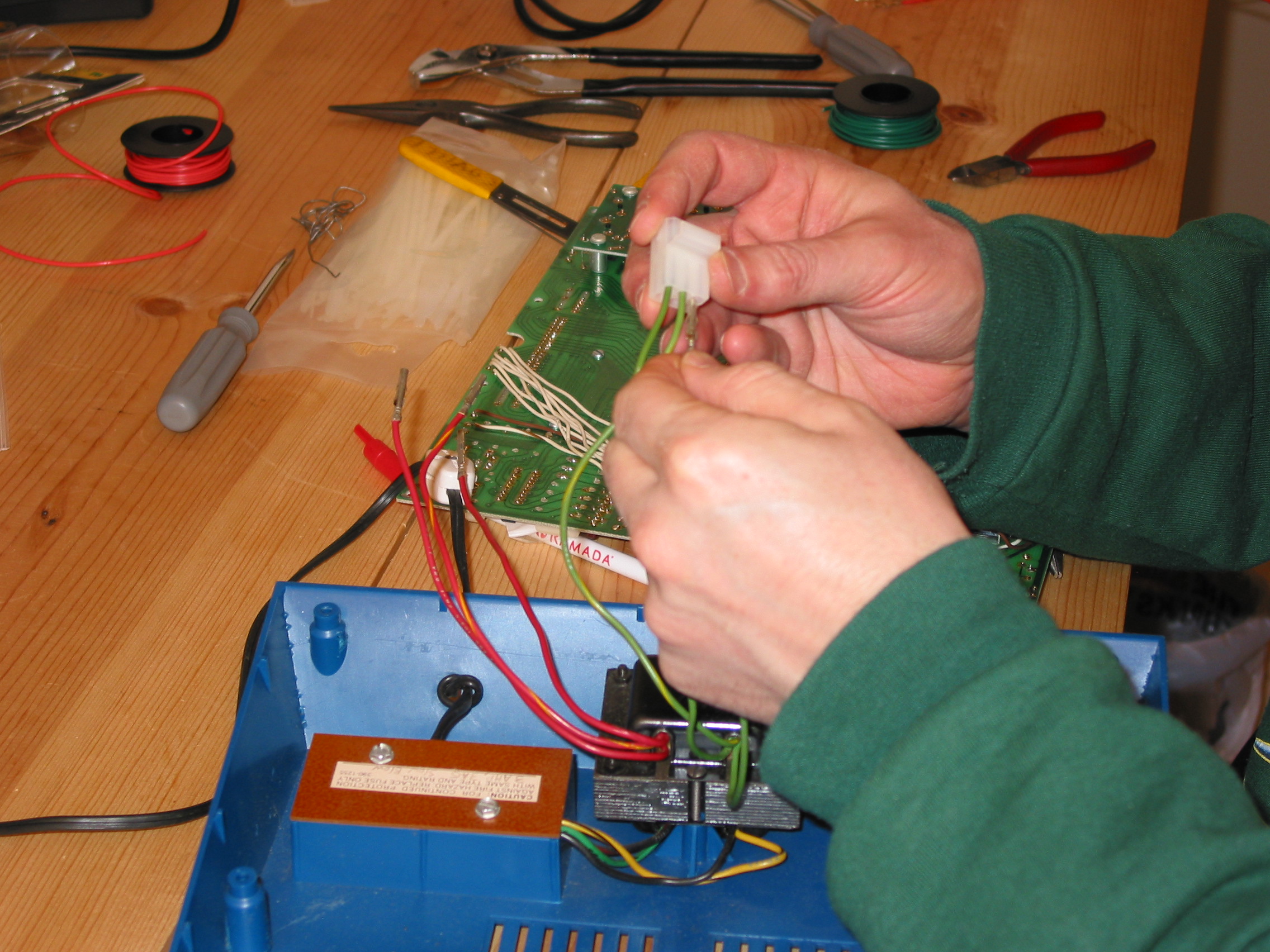
I love that "click".
Final shot of the transformer connector:

An initial attempt to line up this connector with the other connector shows that there is enough length here to reach when everything's all assembled. I was worried about that for a moment.
Major success this evening! I finished the power connector. It's working quite well. The +12V output is: 12.14 VDC .001 VAC. The -12V output is: -11.87 VDC .086 VAC. So apparently less ripple on the +12V output and not much change on the -12V output. I can live with that. Plus, my soldering-power-wires-to-the-circuit-board days are over.
On the advice of Leo from the et-3400 group (Yahoo Groups), I put DeoxIT DN5 down the shaft of the "1" key. (Actually, Leo suggested DeoxIT D5, but DN5 was what I found in Radio Shack.) After a while of repeatedly pressing the key, it works perfectly. One key press, one "1" registers!
As for the 1Hz signal, I straightened out the pins on the LM2901N and reseated it. No go. That part is definitely faulty. I then put in my substitute LM339N, and I've got a pulse! It's a little weird, though. About 26 in one minute (~ 1/2 Hz), and the duty cycle seems to be on about 80%, off 20%. I don't recall the signal being quite that inaccurate back in the day, so maybe I'll order a 2901 from mail-order and check it out later.
So, that covers the three main problems with the ET-3400. I'll put some time into beautification, then I'm not sure if I'll dive right into the ET-3400A or play with the ET-3400 a bit. Maybe I should reconnect with my 6800 machine code days. I've forgotten all the opcodes. Back in the day I had most of them memorized.
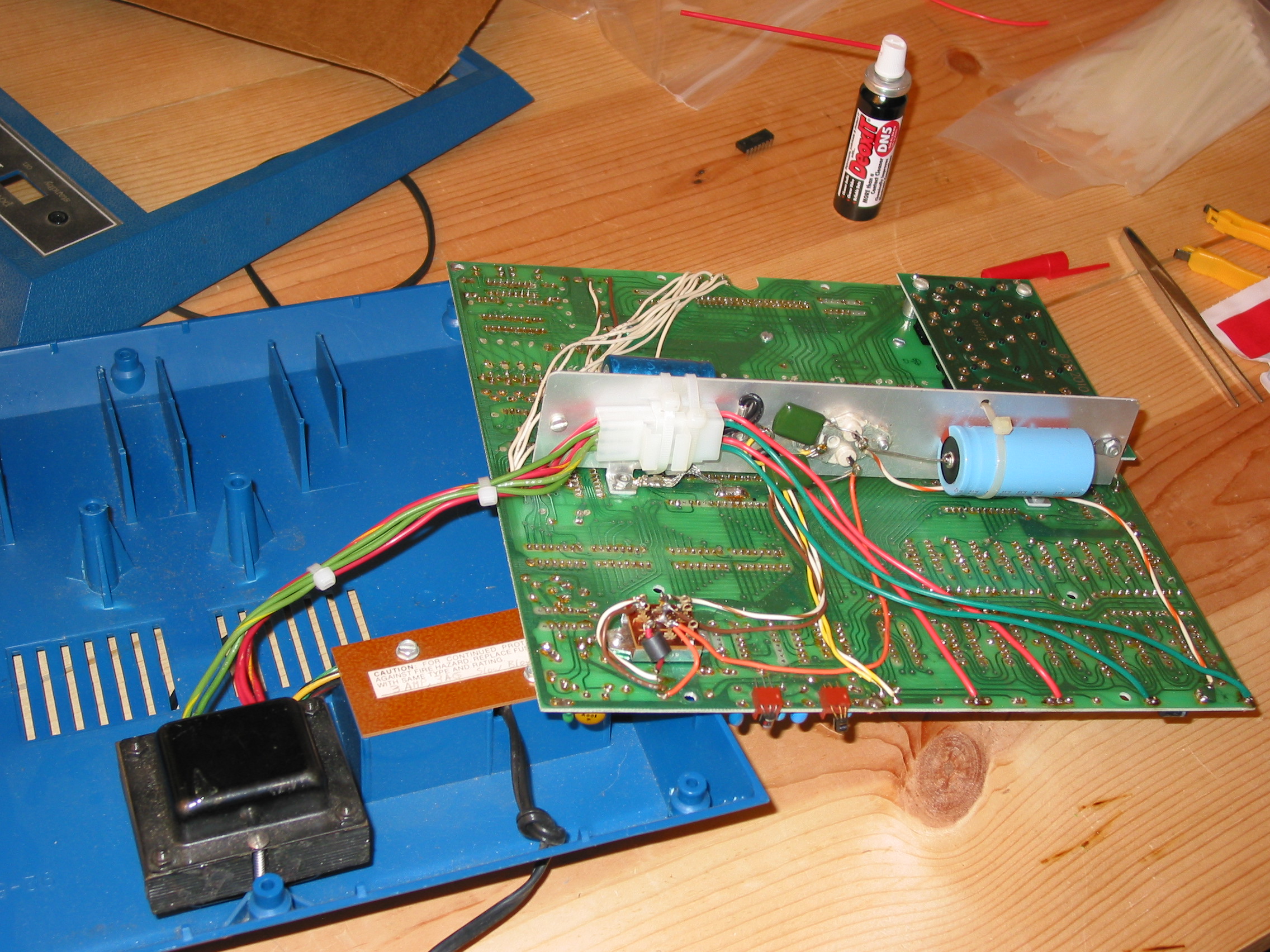
Here's a shot of the power connector all finished. Two zip ties hold it in place quite well. The center taps off the tranformer outputs are both tied to ground, so instead of running wires over to where they used to connect, I soldered them to a lug and screwed it to the chassis. Those are the black wires.
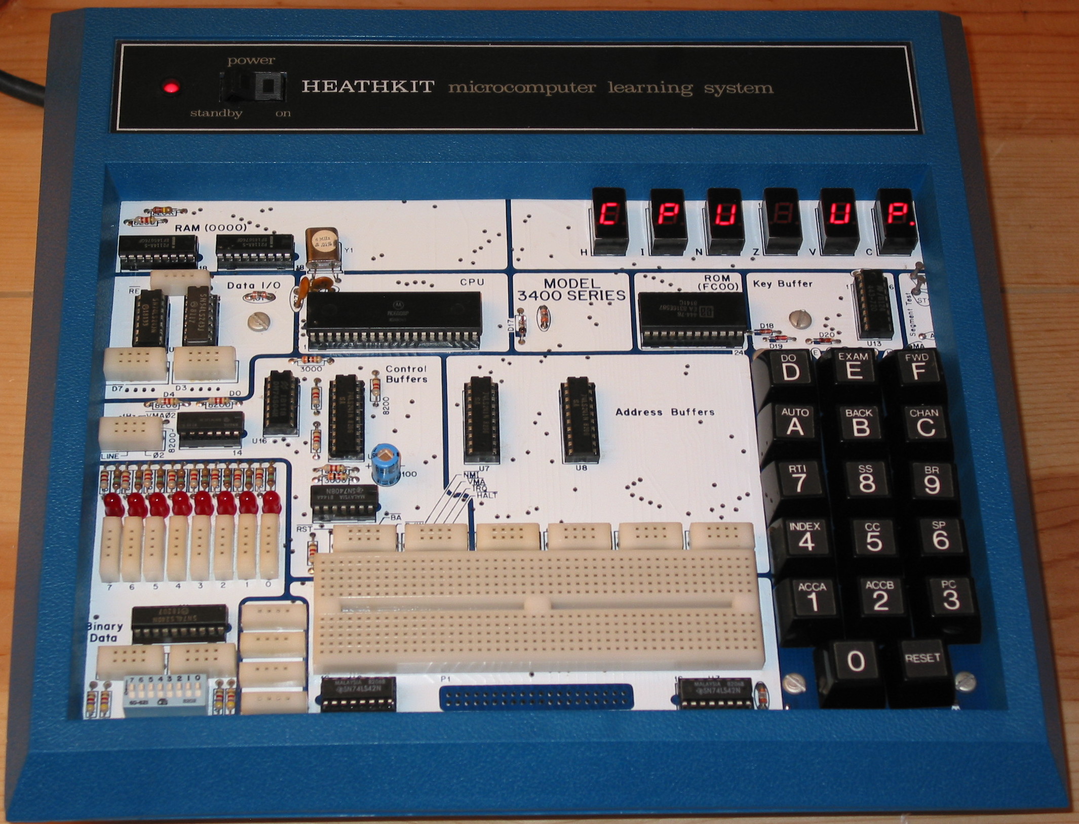
This display, "CPU UP", is very familiar to ET-3400 owners everywhere. It does indicate that a whole lot of things are working properly:

And here's a shot of my "1"s. Look at all those ones.
I spent a little time cleaning up the ET-3400. It doesn't look new, but it does look quite a bit better now. I wasn't planning to post a picture, thinking the change wouldn't be that much when viewed on the screen. But when you compare the pic with the one from Jan 1, you really can see a difference. I also completely reassembled it, even committing to putting back all the screws in the casing.
I haven't come up with a supercool thing to hook up to my ET-3400 or some nifty little program to write. So in order to make progess, I started fixing up the ET-3400A. Almost all the keys had difficulty with not making contact or bouncing pretty bad and giving two or three "presses" for each real press. I treated each keyswitch's post to DeoxIT DN5 and let the fluid run down into the mechanism. Then after pressing all the keys quite a few times, they came to life properly. I'm quite impressed with the DeoxIT product. I also cleaned the keycaps so they're quite spiffy now.
The whole ET-3400A is dusty. It also has a strange odor to it. I purchased this unit off ebay in spring 2010. It seemed like a nice kit and had been well cared for. But it came in a suitcase-like thing made of a thin plastic, which over the years had started to break down and was quite musty. When I received the ET-3400A, the documentation that came with it (schematic, manual, and the books and tapes for the EE-3401 course), and a few parts, I immediately threw away the carrying case. It was that bad. Anyway, this odor still lingers on the unit. I'm hoping that when I get to cleaning the dust off it and wiping it down carefully, the smell goes away mostly.
I finished cleaning up the ET-3400A. I am going to declare it done now. I had been considering doing the same trick to the wires from the transformer for this one as the ET-3400, but I decided against it. First, all the wires appeared to be in good shape and none were broken. Second, the ET-3400A has a grounded 3-conductor power cord, as opposed to the ET-3400's two-conductor non-grounded power cord. In the ET-3400A, the ground wire connects to the transformer and they added a fairly beefy wire braid from there to a big ground pad on the circuit board. I would want to preserve that connection, so would need a different connector than I used on the ET-3400. Again, since there really isn't a problem here, I figured its best to leave it alone.
Here's a picture of the cleaning in progress, note the difference between the "Data I/O" section and the "Control Buffers" section.
And here is the ET-3400A, all done, assembled, ready for action:
I have started refamiliarizing myself with the 6800 and the ET-3400 from a programming point of view. I tried out a simple example from the manual which sequentially displays each segment of the 6 seven-segment LEDs. It worked, but it isn't very satisfying because I didn't write it. I just typed in a bunch of machine code.
To start, I am going to make a simple clock app. There's an example in the manual, but I don't like it because 1) It's based on the CPU clock speed and you adjust a parameter based on whether it runs fast or slow. 2) If you reset the board, the clock stops.
My improved clock program will require a very simple circuit: a single wire from the 60Hz line (based on the AC line frequency, 60Hz here in the US) to the non-maskable interrupt input. The interrupt handler will keep track of the time, and a main routine will display it. If I hit the reset button (and don't hold it down too long), the NMI will keep ticking and keeping time, so I can resume the display part later. I did some experiments with the user NMI vector and verified that the ROM monitor works just fine with the NMI ticking away.
The clock exercise was a success. It's a rudimentary 24-hour clock.
Here's what it looks like:

If you happen to look at the exif data for the picture, you'll see that it was taken at 21:28:10, yet the clock itself says 21:28:31. The heathkit clock is actually the correct one. The exif data is set from my camera's internal clock, which is apparently about 20 seconds slow.
The clock works by taking the line frequency (60Hz in the US) and feeding it into the non-maskable interrupt input. The interrupt vector for the 6800's NMI is in the ROM, but fortunately the authors of the ET-3400 ROM monitor were kind enough to point that vector to a place in RAM, so that experimentors like me can attach to it. The NMI handler does all the math of incrementing the HZ tick count, then seconds, then minutes, then hours appropriately if there's a rollover. I keep the time values in BCD because it's just easier to input the time and for displaying, I can just call a ROM monitor routine to chuck three hex bytes out to the displays. To set the time, I just edit the values in RAM. I can even do this while the ticks are running.
A more correct way would have been to keep the interrupt handler as small and quick as possible. That would mean to have the tick increment a value, roll it over at 60*60*60*24. The display routine would have to be more complicated, taking the tick value from the start of the day, dividing and getting remainders for the seconds, minutes, hours. The 6800 doesn't have a divide instruction and at this point I'm too lazy to write one or dig one up. Plus setting the time would require more code, because editing the raw counter value would be a pain.
Here's the code. If you notice any syntax errors and wonder how on earth I got it to assemble, the answer is that this was hand-assembled. Before I go find an assembler for 6800 that I can work with, I though it would be therapeutic to generate the machine code by hand just once. It really helped me refamiliarize with the 6800 architecture and limitations.
			org	0
		disploop:
0000 bd fc bc		jsr	redis		// reset dig ptr to leftmost
0003 c6 03		ldab	#3
0005 ce 01 00		ldx	#hr
0008 bd fd 7b		jsr	dsplay		// display 3 bytes
000b 3e			wai
000c 7e 00 00		jmp	disploop


00fd			org	$00fd		// nmi user vector
00fd 7e 01 08		jmp	tick


0100			org	$100

0100 00		hr	db	0		// populate these w/ current
0101 00		min	db	0		// time in BCD
0102 00		sec	db	0
0103 00		hz	db	0
0104 24		hrmax	db	$24
0105 60		minmax	db	$60
0106 60		secmax	db	$60
0107 60		hzmax	db	$60

		tick:
0108 ce 01 03		ldx	#hz		// start with the hz value
010b c6 04		ldab	#4		// 4 values to increment
 		loop:
010d a6 00		ldaa	(x+0)		// get value
010f 8b 01		adda	#1		// increment and decimal adjust
0111 19			daa
0112 a1 04		cmpa	(x+4)		// compare to its roll-over value
0114 27 04		beq	roll
0116 a7 00		staa	(x+0)		// no roll, save it and get out
0118 20 06		bra	done
		roll:
011a 6f 00		clr	(x+0)		// roll, clear this value
011c 09			dex			// go to next value
011d 5a			decb			// finished last value?
011e 26 ed		bne	loop
		done:
0120 3b			rti
The NMI ISR (at 0108) runs through a loop incrementing tick counts, seconds, minutes, or hours. The appropriate roll-over values are kept in an array right after the time values, and the ISR uses the index register to access the time value (x) or its rollover value (x+4). In the 6800, the decimal adjust is the BCD magic to keep these values looking like decimal. I have to add 1 using the add instruction because the daa command doesn't work after a simple increment.
The display portion of the program at 0000 makes use of two routines in the ET-3400's ROM monitor. There's a display pointer keeping track of which LED to write to next, and a display routine with dumps a bunch of bytes onto the displays, translating them from their hex values to the special display codes for the 7-segments.
Note to any ET-3400 users out there who are trying this. Do not connect the wire from the Line output to the NMI input until after you have finished entering the program, or at least the ISR part from 00fd through 0120.
I'm going to leave my clock running for a day or so, just to see how it goes.
I didn't want to get too obsessed with the clock program because it was supposed to be just a warmup for something more interesting. However I noticed this morning that the time on the clock wasn't quite right. It had drifted from the clock I set it to the night before. In fact, last night it seemed it had gone fast then this morning too slow. Not by much, only a fraction of a second difference after several hours, I'm quite confused about this. I then realized that the reference clock was the clock in the corner of my iMac, and that might drift and get corrected by NTP at who-knows-when intervals. So I started to compare it to the clock display in a Garmin GPS. The Heathkit clock was definitely going too fast for the period I was watching it.
I'm now running a very simple timing test to ensure that my 60hz signal is really 60hz. The ISR is simply bumping up a 32-bit counter. I noted the time (on the GPS) when I started it. I'll let it run overnight and note the time I stop it by pulling the wire to the NMI. I should be able to calculate exactly how many ticks there were, plus or minus about 20. If I see more error than that, then I'll know that the 60hz signal isn't to be trusted and simply move on. If the 60hz signal is trustworthy, then I don't know what I'll do.
I have considered the possibility that the interrupt service routine is taking too long and not completing before it's invoked again. That would be bad, as the code is definitely not reentrant-safe. Usually, you don't worry about these things because the speed of the cpu is orders of magnitude faster than a huge 1/60 of a second. But is it in this case? I honestly don't know yet. I don't know the exact speed of my cpu, nor have I calculated how long the ISR takes in the worst-case scenario when the hours roll over. When I'm done testing the speed of the 60hz line, I'll do an experiment to determine the clock speed of my 6800. On the ET-3400, the clock circuit is driven by an RC circuit, not by a crystal oscillator. So there's always a bit of variation from one unit to the next.
In the meantime, I have located and built the "asl" assembler on my Mac. This is one amazing piece of software. It can assemble code for dozens of different cpus. (Right now I'm interested in the 6800 but I've got dozens of future projects on other micros.) I managed to convert my clock program to its syntax without too much modification!
The listing looks like this:
 AS V1.41r8 - source file clock.asm - page 1 - 1/12/2011 22:22:12


       1/       0 : =$fcbc              redis	equ	$fcbc
       2/       0 : =$fd7b              dsplay	equ	$fd7b
       3/       0 :
       4/       0 :                     	org	0
       5/       0 :                     disploop:
       6/       0 : bd fc bc            	jsr	redis		; reset dig ptr to leftmost
       7/       3 : c6 03               	ldab	#3
       8/       5 : ce 01 00            	ldx	#hr
       9/       8 : bd fd 7b            	jsr	dsplay		; display 3 bytes
      10/       b : 3e                  	wai
      11/       c : 7e 00 00            	jmp	disploop
      12/       f :
      13/       f :
      14/       f :
      15/      fd :                     	org	$00fd		; nmi user vector
      16/      fd : 7e 01 08            	jmp	tick
      17/     100 :
      18/     100 :
      19/     100 :                     	org	$100
      20/     100 :
      21/     100 : 00                  hr:	byt	0		; populate these w/ current
      22/     101 : 00                  min:	byt	0		; time in BCD
      23/     102 : 00                  sec:	byt	0
      24/     103 : 00                  hz:	byt	0
      25/     104 : 24                  hrmax:	byt	$24
      26/     105 : 60                  minmax:	byt	$60
      27/     106 : 60                  secmax:	byt	$60
      28/     107 : 60                  hzmax:	byt	$60
      29/     108 :
      30/     108 :                     tick:
      31/     108 : ce 01 03            	ldx	#hz		; start with the hz value
      32/     10b : c6 04               	ldab	#4		; 4 values to increment
      33/     10d :                     loop:
      34/     10d : a6 00               	ldaa	0,x		; get value
      35/     10f : 8b 01               	adda	#1		; increment and decimal adjust
      36/     111 : 19                  	daa
      37/     112 : a1 04               	cmpa	4,x		; compare to its roll-over value
      38/     114 : 27 04               	beq	roll
      39/     116 : a7 00               	staa	0,x		; no roll, save it and get out
      40/     118 : 20 06               	bra	done
      41/     11a :                     roll:
      42/     11a : 6f 00               	clr	0,x		; roll, clear this value
      43/     11c : 09                  	dex			; go to next value
      44/     11d : 5a                  	decb			; finished last value?
      45/     11e : 26 ed               	bne	loop
      46/     120 :                     done:
      47/     120 : 3b                  	rti
      48/     121 :
This will really help with the experiments. Funny, I never used an assembler back in the day. I just hand-assembled everything. Now I don't seem to have the patience for it. I'll probably also start working on some faster way to load these programs into memory rather than keying them in.
I let the 60hz-NMI counter run for 19 hours. I was expecting somewhere around 4104000 ticks. I got 4104047 ticks. That's about 3/4 of a second gain in 19 hours. Some of that is can be explained away with perhaps sloppy human start/stop actions, but probably not 3/4 of a second. For now, I'm just going to say that the 60hz signal isn't good enough by itself for time keeping. I should probably let the thing run for a week to know for sure what the drift is on the "60hz" line, but that will have to wait. I want to do other stuff on the ET-3400.
I was curious what the clock speed or cycle time is on my ET-3400. So I did a test that counts. After a set time, I stop the count and see where it is.
 AS V1.41r8 - source file countup.asm - page 1 - 1/13/2011 22:37:11


       1/       0 :                     	org	0
       2/       0 :
       3/       0 : 4f                  	clra
       4/       1 : 97 30               	staa	hi
       5/       3 : 97 31               	staa	hi+1
       6/       5 : 97 32               	staa	lo
       7/       7 : 97 33               	staa	lo+1
       8/       9 :                     tick:
       9/       9 : de 32               	ldx	lo		; 4
      10/       b : 08                  	inx			; 4
      11/       c : df 32               	stx	lo		; 4
      12/       e : 27 08               	beq	dohi		; 4
      13/      10 : 01                  	nop			; 2
      14/      11 : 01                  	nop			; 2
      15/      12 : 01                  	nop			; 2
      16/      13 : 01                  	nop			; 2
      17/      14 : 01                  	nop			; 2
      18/      15 : 01                  	nop			; 2
      19/      16 : 20 f1               	bra	tick		; 4
      20/      18 :                     dohi:
      21/      18 : de 30               	ldx	hi		; 4
      22/      1a : 08                  	inx			; 4
      23/      1b : df 30               	stx	hi		; 4
      24/      1d : 20 ea               	bra	tick		; 4
      25/      1f :
      26/      30 :                     	org	$30
      27/      30 :
      28/      30 : 00 00               hi:	fdb	0
      29/      32 : 00 00               lo:	fdb	0
      30/      34 :
The comments are the number of cpu cycles that each instruction takes. I keep the count in a 32-bit value, so there's a branch to increment the upper half of the value. But doing that would affect the duration of the loop. I added "nop" instructions to the non-branching path to even out the duration. The loop time is constant regardless of whether the upper half of the value is incremented or not.
On the ET-3400, I got 576670 loops in 420 seconds. That's 12563.5 loops/sec. At 32 cpu cycles per loop, that gives 402032 cycles/sec. I recall something about the cpu cycle being 1/2 the cpu frequency. So, this is about right.
On the ET-3400A, I got 7263338 loops in 240 seconds. That results in 968445 cycles/sec. About twice as fast as the ET-3400. That sounds about right.
I didn't calculate the time of the NMI ISR routine in the clock program, but I definitely wasn't exceeding 6700 cycles (1/60th of a second) to execute that routine. So that wasn't the issue. It was just the inaccuracy of the 60hz signal.
I figure I'm done messing about with timing. My next goal is to make it so I can write slightly longer programs and get them into the machines without having to key them in by hand. I want to wire up a serial port and feed the output of the asl assembler directly to the machine. Step 1 is locating the parts I'll need. I know I've got the official Mot 6850 "ACIA" (Asyncronous Communications Interface Adapter) around here somewhere. Here's a picture of the mess I made looking for the parts:

I found a 6850. This was the one that originally came with the Heathkit EE-3402 Microprocessor Interfacing course I purchased a few years after my initial encounter with the ET-3400. I found a second 6850 which I don't remember acquiring, but it's definitely different. It's a ceramic chip, instead of the familiar plastic. I don't know if it works. It would be good to have two. I could hook one to each of the boards. OR, I'm likely to have both on the ET-3400A (which has 2x the memory for a total of 1k bytes!). With two serial ports, I could have one connected to the Mac for downloading programs, and one connected to my next trick. Which is ...
I dusted off (literally!) an HP 7475A pen plotter that I've been carrying around for years. I rescued this from a hallway pile of junk-to-be-thrown-out at IBM Boca Raton in 1992. Soon after I rescued it, I had to purchase a pen carousel and manuals. Every few years, I buy a batch of pens thinking I'm going to do something with this plotter. From the last batch, I have 8 working pens. I've got some colors, but the black ones are all dried up. HP doesn't sell pens for these any more, but there are other suppliers. I'd like to connect the plotter to the ET-3400A and plot something nice.
I have located some more parts for the upcoming serial interface. I found a 74LS138 TTL demuxer and a MC1489 RS232-to-TTL level converter amongst my pile of parts. I didn't find a MC1488, so this will be a receive-only serial interface for a while until I find a 1488. I went to Fry's today in Sacramento and picked up a couple male db9 connectors. I'll solder a few wires onto one and connect to a USB-serial port on the Mac.
I'll build the serial interface circuit tomorrow. I haven't figured out yet what clock frequency it'll need, but I've got a bunch of clock oscillator components. One of them should do the trick.
We have a serial port! I wired up the 6850 ACIA and did some testing. I spent quite a while thinking the whole thing was broken when I could not get any data on the transmit line. I then continued testing everything else which all works just fine. I must have fried the transmitter output at some point in the past on this chip. However, I just decided to focus on the current goal which is to get a serial port that receives so I can download programs easier. The interface is receiving data from my Mac quite well.
Here's a picture:
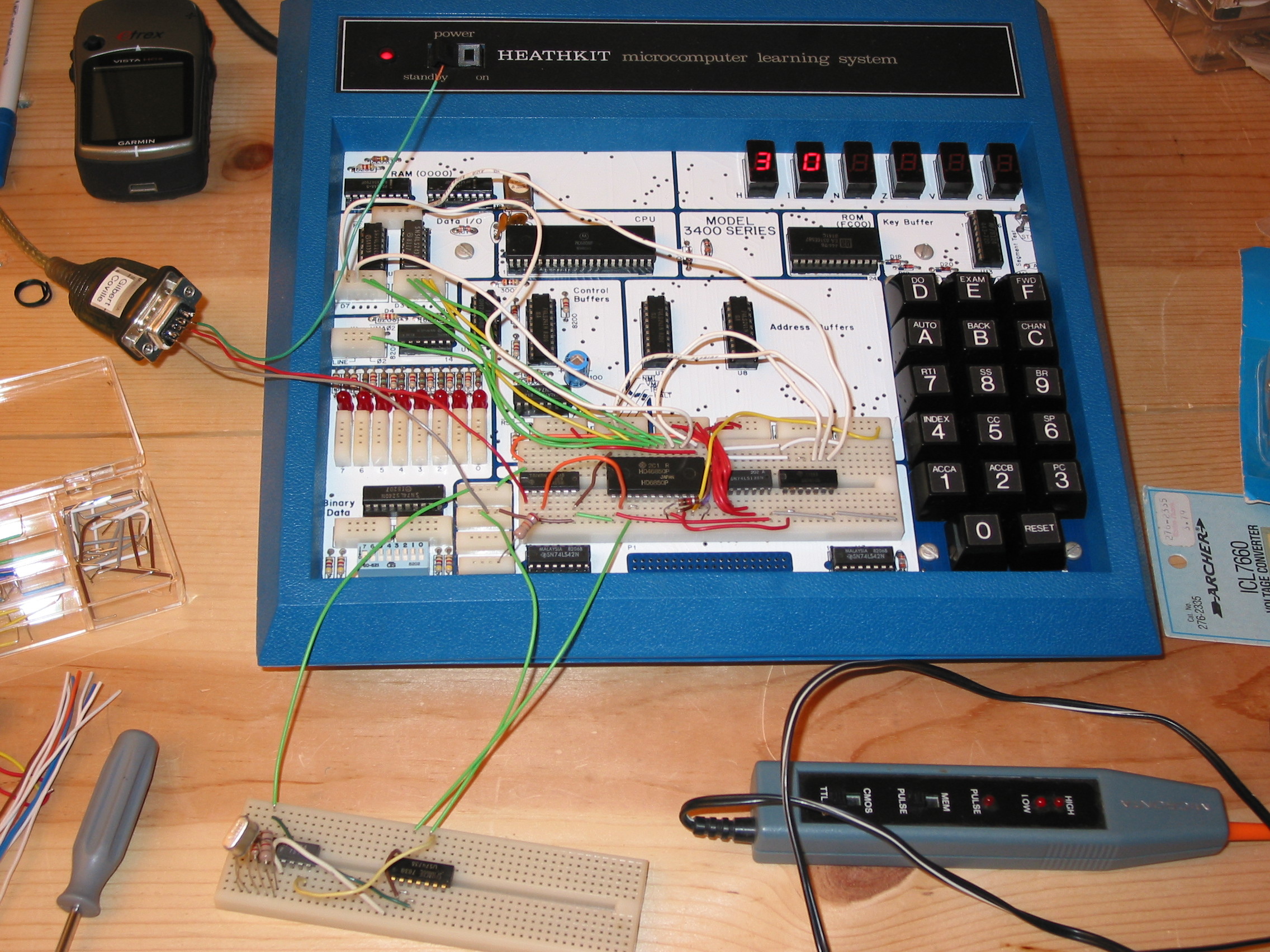
On the proto board on the main unit is the MC1488 level converter, the 6850 ACIA, a 74LS138 3-to-8 demux, and a 7410 triple-input nand gate. On the lower proto board is my clock circuit: a 7404 with a 5.0Mhz crystal and some resistors, and a 7473 flipflop to divide the signal down by 2. To the left is the db9 connected to a USB-serial adapter which goes to the Mac. The demux is connected to Address lines A15 through A10. The 0th output lights up at address 2000h, the 1st output at 2400h, etc. I have the ACIA mapped at 2000h. The 7410 is for glue logic. On this computer, the data lines are available, but they're protected by a directional buffer. That directional control is turned on and off by the "RE-" signal way at the top of the board. We wouldn't need this if we were hooked right into the data bus, but here on the outside we need some glue to set the direction of the external data bus.
The clock frequency was a bit of a challenge. I didn't have such a large selection of crystals and crystal oscillators as I had thought. The 6850 ACIA can take the input clock and divide it by 1, 16, or 64. I found a 5Mhz crystal, set up the circuit for it, and divide it by two. If I set up the ACAI to divide by 64, then I get 5.0Mhz / 2 / 64 = 39062.5, which is only 1.7% different from 38400 baud. It's not great, but it's close enough. I did find a 6.144 Mhz crystal, which when divided by 10, and then use the /16 in the ACIA would give 38400 exactly. Unfortunately, I don't have the right part hanging around to divide by 10.
The program is quite simple:
 AS V1.41r8 - source file serbytes.asm - page 1 - 1/15/2011 22:19:31


       1/       0 : =$fcbc              redis	equ	$fcbc
       2/       0 : =$fe20              outbyt	equ	$fe20
       3/       0 :
       4/       0 : =$2000              sercsr	equ	$2000
       5/       0 : =$2001              serdata	equ	$2001
       6/       0 :
       7/       0 :                     	org	0
       8/       0 : 86 03               	ldaa	#3		; code to reset ACIA
       9/       2 : b7 20 00            	staa	sercsr
      10/       5 : 86 16               	ldaa	#$16		; interrupts off, 8N1, div by 64
      11/       7 : b7 20 00            	staa	sercsr
      12/       a :                     inloop:
      13/       a : b6 20 00            	ldaa	sercsr		; check for byte received
      14/       d : 84 01               	anda	#1
      15/       f : 27 f9               	beq	inloop
      16/      11 : b6 20 01            	ldaa	serdata		; retrieve received byte
      17/      14 : bd fc bc            	jsr	redis		; reset display pointer
      18/      17 : bd fe 20            	jsr	outbyt		; show received byte on left two LEDs
      19/      1a :
      20/      1a : 20 ee               	bra	inloop
      21/      1c :
What you see on the display is hex 30. I had just pressed a "0" in my zterm program on the Mac.
I didn't get as far today as I would have liked. I was hoping to get to the point where I could download the ouput of the assembler on the Mac to the ET-3400A. I've got all the pieces working, but there's a bit of programming to do.
I go on business travel tomorrow and won't be back until Friday so I probably won't be able to work on the project until then. While I'm away, I may try to find a free circuit drawing program so I can show what's really going on with the serial port circuit in the picture above.
I'm out of town and not able to play with my boards, but I've been learning what I can about the asl assembler. I'm preparing for when I return and start wanting to download assembled output directly to the ET-3400A. asl output is in a "p" file which is not straight binary output. Because asl is an assembler for multiple processors, the p files have all sorts of information in them that I don't want. There is a p2hex program that can convert the raw output to a variety of formats, including Motorola S records. However, one goal for my downloading project is the receiving program has to be dead simple because that part I'm going to have to key in by hand every time I unplug the board. I may end up using the p2bin program instead. That is intended for preparing p files to be burned to eproms.
I've been wondering what my options are in getting some sort of free C compiler working for the 6800 board. It turns out that I'm at a company meeting where that are at least 2 dozen very smart gcc compiler engineers. I got plenty of suggestions: Small C, LCC, and SDCC. I took a look at these and I think I'll try to give SDCC a whirl. It builds on MacOS X (in fact, they even deliver a binary for MacOS X). It also targets a few 8-bit cpus, one of which is 68HC08. Off-hand, I don't recall how different the 68HC08 is from the 6800 that's on my boards, but even if it's not the same, I might be able to hack on the compiler to retarget it for 6800.
I'm still out of town. I played around with the sdcc C compiler a bit. It can target the 68hc08, however that's not going to be much help. After doing some research, I found that the hc08 is similar to the 6800, but there are enough differences that make any code for the hc08 unusable on a 6800. sdcc is definitely a cool package, though. There is a compiler, assembler, linker, and simulator. It is possible to retarget the compiler to the 6800 which I hope to do someday, but that's going to be a much bigger effort than I want to get involved with during this winter warmup.
For high-level-like programming, I will be using the macro capabilities in the asl assembler. I don't have a running version of asl with me, but I've been looking at the documentation in preparation for my return to et-3400 civilization.
I'm back at home and hacking away on the serial downloader project. I rearranged the circuit a bit so that received characters issue an interrupt that goes to the NMI on the ET-3400A. I adjusted the program to match. I was then playing around with asl's p2hex program to generate the files suitable to download to the ET-3400A. The p2hex program can produce Motorola S records or Intel hex format. Although I'm using a Motorola 6800, I planned to use Intel hex format because it's simpler. For example, the output of my "countup" program the other day looks like this in S records:
S0030000FC
S5030001FB
S12200004F9730973197329733DE3208DF32270801010101010120F1DE3008DF3020EACE
S5030001FB
S107003000000000C8
S9030000FC
And this in Intel hex:
:1F0000004F9730973197329733DE3208DF32270801010101010120F1DE3008DF3020EAD2
:0400300000000000CC
It's just a colon, length, address, zero-byte, data, and checksum. There's too much additional junk I don't need in the S records format.
I started writing a parser for the Intel hex format in 6800 assembly language, looking for digits, A-F, colons, keeping track of nybbles, byte counts, etc. Things were going well but it didn't take too long before it was at 200 bytes. And it's only about 1/2 done. Well, I just don't have a whole lot of usable memory in these things (197+256 bytes in the ET-3400, and an additional 512 bytes in the ET-3400A). I don't want to spend that much of it on a downloader for two reasons. The downloader is the part that I have to key in manually and it wouldn't leave much room for "real" programs.
I'm now thinking of going with a very simple downloader. No parsing. Just grab sets of [address, count, data...]... I've got an 8-bit-clean serial port, so it'll be two chars for address, one for count, and one each for the data bytes. It will require a preparation program on my iMac development host, but that should be pretty easy. This will have to be tomorrow's goal.
I finished the simple downloader and it's working pretty well. It sits in memory and the NMI from the serial port invokes an interrupt service routine (ISR) which reads address, length, and data bytes. Then it repeats waiting for another set of address, length, and data bytes. The routine has to keep a "state" byte to know where it is in the sequence so that when the ISR is invoked again, it knows where it was in the sequence.
I use a couple assembler features. The ENUM pseudo-op is a straightforward method to assign constant values to symbols. I also use a simple macro called "irp" which iterates over parameters to generate some code. Here's the listing:
 AS V1.41r8 - source file rcvbytes.asm - page 1 - 1/22/2011 13:08:31


       1/       0 :                     	PAGE	0
       2/       0 :
       3/       0 : =$fcbc              redis	equ	$fcbc
       4/       0 : =$fe20              outbyt	equ	$fe20
       5/       0 :
       6/       0 : =$2000              sercsr	equ	$2000
       7/       0 : =$2001              serdata	equ	$2001
       8/       0 :
       9/       0 : =$0..$3             	ENUM	ready, addrhi, addrlo, len
      10/      fd :                     	org	$fd
      11/      fd : 7e 01 98            	jmp	rxint
      12/     100 :
      13/     180 :                     	org	$180
      14/     180 : 20 04               	bra	start
      15/     182 :
      16/     182 : 00                  state:	fcb	0		; what state parser is in
      17/     183 : 00                  count:	fcb	0		; how many bytes to receive
      18/     184 : 00 00               addr:	fdb	0		; current address
      19/     186 :
      20/     186 :                     start:
      21/     186 : 86 00               	ldaa	#ready
      22/     188 : b7 01 82            	staa	state
      23/     18b :
      24/     18b : 86 03               	ldaa	#3		; ACIA master reset
      25/     18d : b7 20 00            	staa	sercsr
      26/     190 : 86 96               	ldaa	#$96		; rxint on, rts- low, txint off, 8N1, div by 64
      27/     192 : b7 20 00            	staa	sercsr
      28/     195 :                     end:
      29/     195 : 3e                  	wai
      30/     196 : 20 fd               	bra	end
      31/     198 :
      32/     198 :                     rxint:
      33/     198 : f6 20 01            	ldab	serdata		; retrieve received byte
      34/     19b : b6 01 82            	ldaa	state
      35/     19e :
      36/     19e :                     	irp	state, ready, addrhi, addrlo, len
      37/     19e :                     	cmpa	#state
      38/     19e :                     	beq	do_state
      39/     19e :                     	endm
      37/     19e : 81 00                       cmpa    #READY
      38/     1a0 : 27 0e                       beq     do_READY
      37/     1a2 : 81 01                       cmpa    #ADDRHI
      38/     1a4 : 27 11                       beq     do_ADDRHI
      37/     1a6 : 81 02                       cmpa    #ADDRLO
      38/     1a8 : 27 14                       beq     do_ADDRLO
      37/     1aa : 81 03                       cmpa    #LEN
      38/     1ac : 27 17                       beq     do_LEN
      40/     1ae :
      41/     1ae : 20 28               	bra	rxintdone
      42/     1b0 :
      43/     1b0 :                     do_ready:
      44/     1b0 : f7 01 84            	stab	addr
      45/     1b3 : 86 01               	ldaa	#addrhi
      46/     1b5 : 20 1e               	bra	newstate
      47/     1b7 :
      48/     1b7 :                     do_addrhi:
      49/     1b7 : f7 01 85            	stab	addr+1
      50/     1ba : 86 02               	ldaa	#addrlo
      51/     1bc : 20 17               	bra	newstate
      52/     1be :
      53/     1be :                     do_addrlo:
      54/     1be : f7 01 83            	stab	count
      55/     1c1 : 86 03               	ldaa	#len
      56/     1c3 : 20 10               	bra	newstate
      57/     1c5 :
      58/     1c5 :                     do_len:
      59/     1c5 : fe 01 84            	ldx	addr
      60/     1c8 : e7 00               	stab	0,x
      61/     1ca : 08                  	inx
      62/     1cb : ff 01 84            	stx	addr
      63/     1ce : 7a 01 83            	dec	count
      64/     1d1 : 26 05               	bne	rxintdone
      65/     1d3 : 86 00               	ldaa	#ready
      66/     1d5 :                     ;	bra	newstate
      67/     1d5 :
      68/     1d5 :                     newstate:
      69/     1d5 : b7 01 82            	staa	state
      70/     1d8 :
      71/     1d8 :                     rxintdone:
      72/     1d8 : 3b                  	rti
      73/     1d9 :
There are a few more efficiencies I could take with the state handling, decrementing instead of comparing, etc. I may do that, because this part of the program needs to be keyed in manually, so every byte saved helps.
So, here's a little sample program copied verbatim from the Heathkit Manual for the Microprocessor Trainer ET-3400 page 55. It goes through a loop displaying all the segments on the LEDs. I've edited it so the syntax matches my assembler, but other than that it is unmodified.
 AS V1.41r8 - source file sample1.asm - page 1 - 1/22/2011 13:26:02


       1/       0 :                     ;		Sample 1
       2/       0 :                     ;	Turn on and off each segment in
       3/       0 :                     ;	sequence beginning at H display
       4/       0 :                     ;	Uses monitor subroutines REDIS and OUTCH
       5/       0 :                     ;	Note: One dp in each display is active
       6/       0 :
       7/       0 : =$fcbc              redis	equ	$fcbc
       8/       0 : =$fe20              outbyt	equ	$fe20
       9/       0 : =$fe3a              outch	equ	$fe3a
      10/       0 : =$f0                digadd	equ	$f0
      11/       0 :
      12/       0 : bd fc bc            start	jsr	redis		; set up first display address
      13/       3 : 86 01               	ldaa	#$01		; first segment code
      14/       5 : 20 07               	bra	out
      15/       7 : d6 f1               same	ldab	digadd+1	; fix display address
      16/       9 : cb 10               	addb	#$10		; for next segment
      17/       b : d7 f1               	stab	digadd+1
      18/       d : 48                  	asla			; next segment code
      19/       e : bd fe 3a            out	jsr	outch		; output segment
      20/      11 : ce 2f 00            	ldx	#$2f00		; time to wait
      21/      14 : 09                  wait	dex
      22/      15 : 26 fd               	bne	wait		; time out yet?
      23/      17 : 16                  	tab
      24/      18 : 5d                  	tstb			; last segment this display?
      25/      19 : 26 ec               	bne	same		; next segment
      26/      1b : 86 01               	ldaa	#$01		; reset segment code
      27/      1d : de f0               	ldx	digadd		; next display
      28/      1f : 8c c1 0f            	cpx	#$c10f		; last display yet?
      29/      22 : 26 ea               	bne	out
      30/      24 : 20 da               	bra	start		; do again
      31/      26 :
And here is its generated code in Intel Hex format:
:10000000BDFCBC86012007D6F1CB10D7F148BDFE60
:100010003ACE2F000926FD165D26EC8601DEF08C17
:06002000C10F26EA20DA00
:00000001FF
I wrote a program to convert this format into a file that has just address, length, and data bytes in it. I wrote it in C, which isn't the greatest language for easy string manipulation, but it's the "hammer" I've got handy in my toolbox. If you want to look at it, it's called ihextoxfr.c. Comments are pretty sparse at this point, but it loops through the lines of the intel hex format, digesting the ascii hex digits and figuring out their values. Then for each line it spits out the address, length, and data bytes in binary. These will be sent directly down the serial port to the ET-3400A.
Here's what the output of the ihex2xfr program looks like when shown through hexdump.
$ ihextoxfr < sample1.hex > sample1.xfr
$ hexdump sample1.xfr
0000000 00 00 10 bd fc bc 86 01 20 07 d6 f1 cb 10 d7 f1
0000010 48 bd fe 00 10 10 3a ce 2f 00 09 26 fd 16 5d 26
0000020 ec 86 01 de f0 8c 00 20 06 c1 0f 26 ea 20 da
000002f
So you can see the first line of intel hex has an address 0000, 10h bytes, and then the data bytes starting with "bd" and ending with "fe".
This ".xfr" file is then sent down the serial port using the "Send Text" mechanism of the Zterm serial program I'm using on the Mac.
I made a movie:
We've got a week left in the challenge. It's time to start really doing something! Sure, I've got my ET-3400 and ET-3400A repaired and cleaned up. I got a nice cross-development environment going on the ET-3400A. Although that seemed pretty cool to me because it will speed up my development, it is not actually cool to anyone else, except maybe the random ET-3400 owner who might wander by. It's just an enabler for cool. Real cool is still to come, I hope.
With the remaining time, I would like to do at least one pure software project on the ET-3400A. I haven't decided what, yet, but I'm sure something will come up. However, with just over 300 bytes of ram to work with, it will be a challenge. I mistakenly thought that the ET-3400A had more memory than the ET-3400. This was a reasonable assumption, since the ET-3400A has 2x 2114 static ram parts yielding 1k, whereas the ET-3400 has 4x 2112 static ram parts yielding 512 bytes. Unfortunately, the ET-3400A was designed to be an updated version of the ET-3400, so the upper half of the 1k isn't available. (I found this out after keying in a program to 0x200, only to find it wasn't there. A quick check of the ET-3400A schematic and sure enough, the address logic is for 512 bytes only, and A9 on the 2114's is grounded.)
I'd also like to do some nifty hardware things. You might recall I mentioned a HP 7475A plotter. You might also recall that the transmit data line on my 6850 UART is inoperative. I made several attempts to get it going yesterday, but it just won't budge. I'm pretty sure it's broken. I could order a new 6850 off ebay or from Jameco or something like that, but it probably wouldn't arrive in time unless I pay for expedited shipping. I'm too cheap. I will probably order a replacement eventually, but after the winter warmup is over. Currently, I do have a working "RTS" output line, so I could twiddle the signal manually at the correct rate to transmit characters to the plotter.
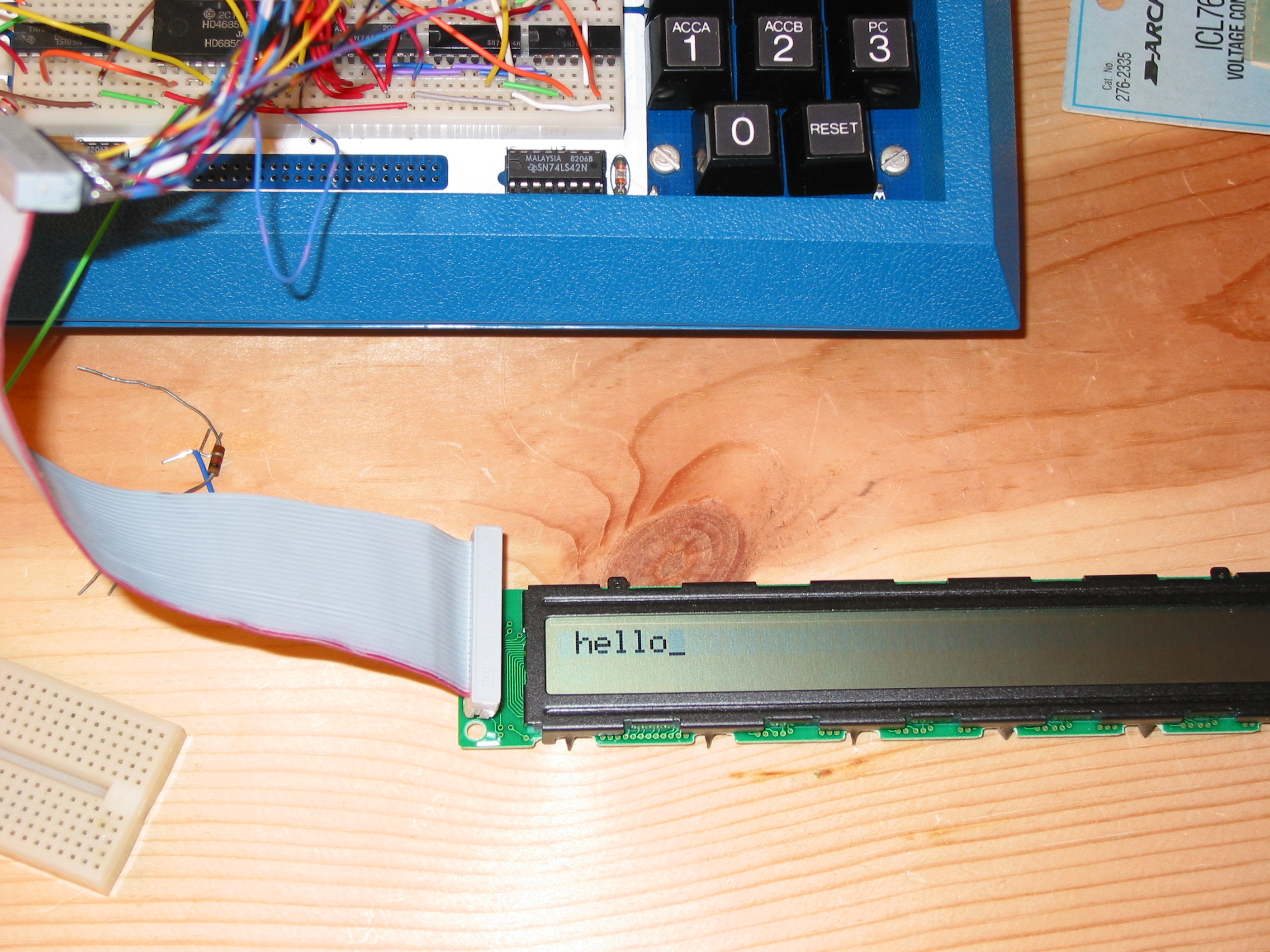
I have also dug up an Optrex DMC-40218 2-line by 40-character LCD module that I picked up about 20 years ago. I had never tried to get it work before, so I had no idea if it was functional or not. Yesterday, I did manage to find the operating instructions for it on the internet. Today, I rearranged my interface circuit a bit, checked to ensure the serial port was still working, and then spent about 2 hours figuring out why the serial port wasn't working anymore. It turns out I had borked it yesterday with my experiments to get the transmitter going.
Now that is all sorted out, the basic interface to the LCD seems to be functional. There's quite a bit of controlling to it, and I haven't quite mastered it yet. I did manage to get a "hello" to display once simply by manually poking at the control and data registers, but haven't done any programming to it yet.
Here's what it looks like:
I've got the LCD figured out. You send various things to a control register, then send the display data to the data register. Once I figured out the right bits to set in the control register, it came together nicely. There are some nifty features such as quickly scrolling the characters on the display left or right. There are also 8 loadable character slots, so you can make your own character patterns.
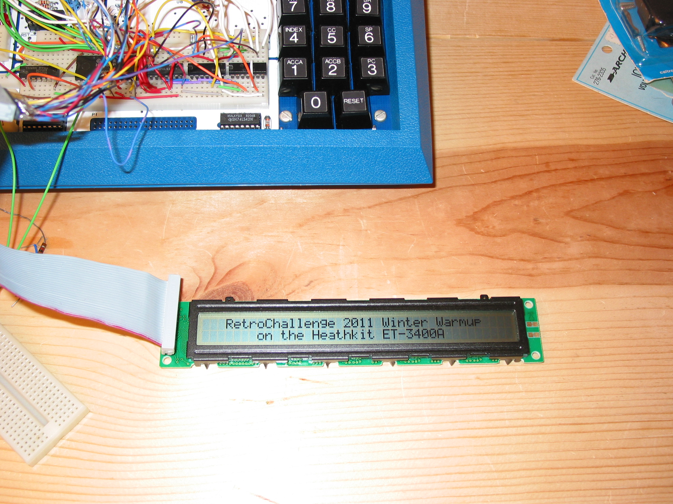
Here's the program that displayed that:
 AS V1.41r8 - source file lcd_demo1.asm - page 1 - 1/25/2011 22:28:56


       1/       0 :                     	PAGE	0
       2/       0 :
       3/       0 :
       4/       0 : =$2400              lcdctl	equ	$2400
       5/       0 : =$2401              lcddata	equ	$2401
       6/       0 :
       7/       0 :                     	org	0
       8/       0 :
       9/       0 : 20 48               	bra	start
      10/       2 :
      11/       2 :                     chardata:
      12/       2 :                     ;		 ----------------------------------------
      13/       2 : 20 20 20 52 65 74   	fcb	"   RetroChallenge 2011 Winter Warmup    "
                    72 6f 43 68 61 6c
                    6c 65 6e 67 65 20
                    32 30 31 31 20 57
                    69 6e 74 65 72 20
                    57 61 72 6d 75 70
                    20 20 20 20
      14/      2a : 20 20 20 20 20 20   	fcb	"       on the Heathkit ET-3400A"
                    20 6f 6e 20 74 68
                    65 20 48 65 61 74
                    68 6b 69 74 20 45
                    54 2d 33 34 30 30
                    41
      15/      49 :                     ;		 ----------------------------------------
      16/      49 : 00                  	fcb	0
      17/      4a :
      18/      4a :                     start:
      19/      4a : 86 38               	ldaa	#$38		; 8bit interface, 2-line display, 5x7 chars
      20/      4c : 8d 1c               	bsr	sendctl
      21/      4e :
      22/      4e : 86 01               	ldaa	#$1		; clear display
      23/      50 : 8d 18               	bsr	sendctl
      24/      52 :
      25/      52 :
      26/      52 : 86 0c               	ldaa	#$0c		; display on, cursor off, blink off
      27/      54 : 8d 14               	bsr	sendctl
      28/      56 :
      29/      56 : ce 00 02            	ldx	#chardata
      30/      59 : 8d 03               	bsr	display
      31/      5b :
      32/      5b :                     done:
      33/      5b : 3e                  	wai
      34/      5c : 20 fd               	bra	done
      35/      5e :
      36/      5e :                     display:
      37/      5e : 36                  	psha
      38/      5f :                     display_lp:
      39/      5f : a6 00               	ldaa	0,x		; get char to display
      40/      61 : 27 05               	beq	display_done	; check for zero byte at end of string
      41/      63 : 8d 12               	bsr	senddata
      42/      65 : 08                  	inx			; point to next char
      43/      66 : 20 f7               	bra	display_lp
      44/      68 :                     display_done:
      45/      68 : 32                  	pula
      46/      69 : 39                  	rts
      47/      6a :
      48/      6a :                     sendctl:
      49/      6a : 36                  	psha
      50/      6b :                     sendclp:
      51/      6b : b6 24 00            	ldaa	lcdctl		; check for busy bit
      52/      6e : 84 80               	anda	#$80
      53/      70 : 26 f9               	bne	sendclp
      54/      72 : 32                  	pula
      55/      73 : b7 24 00            	staa	lcdctl		; send value to control register
      56/      76 : 39                  	rts
      57/      77 :
      58/      77 :                     senddata:
      59/      77 : 36                  	psha
      60/      78 :                     senddlp:
      61/      78 : b6 24 00            	ldaa	lcdctl		; check for busy bit
      62/      7b : 84 80               	anda	#$80
      63/      7d : 26 f9               	bne	senddlp
      64/      7f : 32                  	pula
      65/      80 : b7 24 01            	staa	lcddata		; send value to data register
      66/      83 : 39                  	rts
      67/      84 :
After getting the LCD going and putting up the sample display, I realized two things:
1) I don't like having the downloader running in the background. Any time I've got Zterm running on the Mac, if I accidentally hit some keys in that program, they get sent to the ET-3400A and the downloader starts interpreting them as address, length, etc. Also, because the ISR had to save the state of where in the byte stream it was, I was never sure that it was in the proper state to just start using again (waiting for an address). So I was often resetting and running the init routine in it anyway. Additionally, I think I'd like to use the serial port to receive some data other than downloaded code. For instance, I can get keyboard input from my Mac's keyboard to the ET-3400A over the serial port quite nicely. So, I have disabled the NMI from the serial port and now go with polling. The program doesn't have to keep track of downloading state, and the downloader is much simpler now. As an added bonus, when I have to key it in manually, it goes quicker because it's shorter than before.
 AS V1.41r8 - source file rcvsimple.asm - page 1 - 1/26/2011 22:19:33


       1/       0 :                     	PAGE	0
       2/       0 :
       3/       0 : =$fcbc              redis	equ	$fcbc
       4/       0 : =$fe20              outbyt	equ	$fe20
       5/       0 :
       6/       0 : =$2000              sercsr	equ	$2000
       7/       0 : =$2001              serdata	equ	$2001
       8/       0 :
       9/      80 :                     	org	$0080
      10/      80 :                     start:
      11/      80 :
      12/      80 : 86 03               	ldaa	#3		; ACIA master reset
      13/      82 : b7 20 00            	staa	sercsr
      14/      85 : 86 16               	ldaa	#$16		; rxint off, rts- low, txint off, 8N1, div by 64
      15/      87 : b7 20 00            	staa	sercsr
      16/      8a :
      17/      8a :                     getaddr:
      18/      8a : 8d 15               	bsr	getbyte		; get two address bytes
      19/      8c : 97 ac               	staa	temp
      20/      8e : 8d 11               	bsr	getbyte
      21/      90 : 97 ad               	staa	temp+1
      22/      92 : de ac               	ldx	temp		; hold in index register
      23/      94 :                     getlen:
      24/      94 : 8d 0b               	bsr	getbyte		; get length byte
      25/      96 : 16                  	tab			; hold in accumulator b
      26/      97 :
      27/      97 :                     bytelp:
      28/      97 : 8d 08               	bsr	getbyte		; get a data bytes
      29/      99 : a7 00               	staa	0,x		; save it at current address
      30/      9b : 08                  	inx			; point to next address
      31/      9c : 5a                  	decb			; loop while count > 0
      32/      9d : 26 f8               	bne	bytelp
      33/      9f :
      34/      9f : 20 e9               	bra	getaddr		; go back to waiting for address byte
      35/      a1 :
      36/      a1 :                     getbyte:
      37/      a1 : b6 20 00            	ldaa	sercsr		; retrieve status register
      38/      a4 : 84 01               	anda	#$01		; check for character received
      39/      a6 : 27 f9               	beq	getbyte
      40/      a8 : b6 20 01            	ldaa	serdata		; read received character
      41/      ab : 39                  	rts
      42/      ac :
      43/      ac : 00 00               temp:	fdb	0
      44/      ae :
45 fewer bytes to key in.
2) I'm starting to feel confined in the mere 256+197 bytes of memory. (59 bytes are used by the monitor ROM.) I wanted to do some animations on the LCD and quickly ran out of memory when I was coding it. I have therefore added to my frankenstein mess and added 2K of memory. I had four 2114 1k-by-4bit static ram parts hanging around. So, with more wire, a little more glue logic, and those 2114's, I've got 2K more RAM. It's contiguous, too, from 2800-2FFF. If I do this 61439 more times, I'll have 120M, just like the nice maxed-out DECstation I saw recently.
But seriously, 2k is really quite a luxury in this environment. Here's a picture of the monster in its current form:

The memory board is at the top. The ET-3400A is running a program that takes keys over the serial port and dumps them to the LCD. It shows the hex value of the last key on the LEDs at the top. Here's the code. There are some extra routines that are currently unused in this program. That's not a problem now since I've got all this memory and a nice downloader now!
 AS V1.41r8 - source file typeme.asm - page 1 - 1/27/2011 21:56:32


       1/       0 :                     	PAGE	0
       2/       0 :
       3/       0 :
       4/       0 : =$2000              sercsr	equ	$2000
       5/       0 : =$2001              serdata	equ	$2001
       6/       0 : =$2400              lcdctl	equ	$2400
       7/       0 : =$2401              lcddata	equ	$2401
       8/       0 :
       9/       0 : =$fcbc              redis	equ	$fcbc
      10/       0 : =$fe20              outbyt	equ	$fe20
      11/       0 :
      12/    2800 :                     	org	$2800
      13/    2800 :
      14/    2800 : 8d 3e               	bsr	initlcd
      15/    2802 : 8d 49               	bsr	initser
      16/    2804 :
      17/    2804 :                     loop:
      18/    2804 : 8d 52               	bsr	getbyte
      19/    2806 : bd fc bc            	jsr	redis
      20/    2809 : bd fe 20            	jsr	outbyt
      21/    280c : 81 08               	cmpa	#$08
      22/    280e : 27 04               	beq	bs
      23/    2810 : 8d 21               	bsr	senddata
      24/    2812 : 20 f0               	bra	loop
      25/    2814 :                     bs:
      26/    2814 : 86 10               	ldaa	#$10
      27/    2816 : 8d 0e               	bsr	sendctl
      28/    2818 : 20 ea               	bra	loop
      29/    281a :
      30/    281a :                     display:
      31/    281a : 36                  	psha
      32/    281b :                     display_lp:
      33/    281b : a6 00               	ldaa	0,x
      34/    281d : 27 05               	beq	display_done
      35/    281f : 8d 12               	bsr	senddata
      36/    2821 : 08                  	inx
      37/    2822 : 20 f7               	bra	display_lp
      38/    2824 :                     display_done:
      39/    2824 : 32                  	pula
      40/    2825 : 39                  	rts
      41/    2826 :
      42/    2826 :                     sendctl:
      43/    2826 : 36                  	psha
      44/    2827 :                     sendclp:
      45/    2827 : b6 24 00            	ldaa	lcdctl
      46/    282a : 84 80               	anda	#$80
      47/    282c : 26 f9               	bne	sendclp
      48/    282e : 32                  	pula
      49/    282f : b7 24 00            	staa	lcdctl
      50/    2832 : 39                  	rts
      51/    2833 :
      52/    2833 :                     senddata:
      53/    2833 : 36                  	psha
      54/    2834 :                     senddlp:
      55/    2834 : b6 24 00            	ldaa	lcdctl
      56/    2837 : 84 80               	anda	#$80
      57/    2839 : 26 f9               	bne	senddlp
      58/    283b : 32                  	pula
      59/    283c : b7 24 01            	staa	lcddata
      60/    283f : 39                  	rts
      61/    2840 :
      62/    2840 :                     initlcd:
      63/    2840 : 86 38               	ldaa	#$38		; 8bit interface, 2-line display, 5x7 chars
      64/    2842 : 8d e2               	bsr	sendctl
      65/    2844 : 86 01               	ldaa	#$1		; clear display
      66/    2846 : 8d de               	bsr	sendctl
      67/    2848 : 86 0e               	ldaa	#$0e		; display on, cursor on, blink off
      68/    284a : 8d da               	bsr	sendctl
      69/    284c : 39                  	rts
      70/    284d :
      71/    284d :                     initser:
      72/    284d : 86 03               	ldaa	#3		; ACIA master reset
      73/    284f : b7 20 00            	staa	sercsr
      74/    2852 : 86 16               	ldaa	#$16		; rxint off, rts- low, txint off, 8N1, div by 64
      75/    2854 : b7 20 00            	staa	sercsr
      76/    2857 : 39                  	rts
      77/    2858 :
      78/    2858 :                     getbyte:
      79/    2858 : b6 20 00            	ldaa	sercsr		; retrieve status register
      80/    285b : 84 01               	anda	#$01		; check for character received
      81/    285d : 27 f9               	beq	getbyte
      82/    285f : b6 20 01            	ldaa	serdata		; read received character
      83/    2862 : 39                  	rts
      84/    2863 :
      85/    2863 :                     pause_save:
      86/    2863 : 00 00               	fdb	0
      87/    2865 :
      88/    2865 :                     pause_long:
      89/    2865 : ff 28 63            	stx	pause_save
      90/    2868 : ce 00 00            	ldx	#0
      91/    286b : 20 0e               	bra	pause_lp
      92/    286d :
      93/    286d :                     pause_medium:
      94/    286d : ff 28 63            	stx	pause_save
      95/    2870 : ce 80 00            	ldx	#$8000
      96/    2873 : 20 06               	bra	pause_lp
      97/    2875 :
      98/    2875 :                     pause_short:
      99/    2875 : ff 28 63            	stx	pause_save
     100/    2878 : ce 40 00            	ldx	#$4000
     101/    287b :                     pause_lp:
     102/    287b : 09                  	dex
     103/    287c : 26 fd               	bne	pause_lp
     104/    287e : fe 28 63            	ldx	pause_save
     105/    2881 : 39                  	rts
     106/    2882 :
Often when there's a bug in an ET-3400A program, the CPU gets loose and starts executing random things as if they were code. Sometimes when this happens, everything in RAM gets overwritten. That means that I have to key in the downloader by hand again, re-download the offending code, and start debugging.
When this happened 3 or 4 times in about 10 minutes, I figured there had to be a better way. One solution is to put the downloader into EPROM and wire it up. Another is to make the downloader extremely simple. I chose the latter. My simple downloader is 14 bytes long. I then use this to download the more complete downloader, which I've spiffed up to flash the LEDs while things are downloading. Then I download the real programs.
 AS V1.41r8 - source file rcvsimple.asm - page 1 - 1/29/2011 22:37:06


       1/       0 :                     ; You need to manually reset the serial port w/ #$3 and #$16 at $2000
       2/       0 :                     ; and put the destination address in the index register
       3/       0 :
       4/       0 : =$2000              sercsr	equ	$2000
       5/       0 : =$2001              serdata	equ	$2001
       6/       0 :
       7/       0 :                     	org	0
       8/       0 :                     bytelp:
       9/       0 : b6 20 00            	ldaa	sercsr		; retrieve status register
      10/       3 : 84 01               	anda	#$01		; check for character received
      11/       5 : 27 f9               	beq	bytelp
      12/       7 : b6 20 01            	ldaa	serdata		; read received character
      13/       a : a7 00               	staa	0,x		; save it at current address
      14/       c : 08                  	inx			; point to next address
      15/       d : 20 f1               	bra	bytelp
      16/       f :
The real downloader's binary file needs to be modified a bit to strip off the address and length bytes at the beginning, but that's done easily with:
tail +4c /tmp/$1.xfr > $1.xfr
The exciting news today is that I have a working serial output port. You may recall that the Tx line on my 6850 ACIA isn't functioning. I also didn't have the 1488 line driver to go with it. However, I did find a Motorola MC145407P single supply 3-in/3-out RS232 interface. I got a couple sample parts about 25 years ago. I think this was Mot's response to the Maxim MAX-232 devices. It's one of those interfaces where you give it +5V, hook up some capacitors and it uses charge pumps to produce its own +10V/-10V. I didn't want to put on the capacitors and since I have +12V/-12V supplies handy, I just hooked those to the correct voltage pins. The in and out drivers seem to be working okay.
As far as the Tx line on the ACIA not working, that's a different problem. I do have a functioning RTS line, so I figured I can just wiggle that line at the right rate with the correct data to make my own serial port. I wrote up the code which rolls the bits out of one of the accumulators, rolls each one into the other accumulator, moves it around and builds a proper control word for the ACIA, spits it out, then waits for a time to be determined so that it matches the right baud rate. I tried it out with a very long wait so I could watch it. It seemed to have the bits all correct. I then set out to calculate the delay to put in the bit loop to send bits at 1/38400'th of a second. I know the basic cycle time of the ET-3400A, and how many cycles there were in the existing part of the bit loop.
It turned out that my machine is so slow, using this method I could not get the bits out at 38400 baud! I had to rearrange the routine so that it prepares a list of the bytes to send to the ACIA's control port. Then when it comes time to send the bits over the RTS line, I can run through that list quickly. There was enough time to spare so that 3 NOP commands completed the loop for 38400 baud. (I also added some code so that I can output bytes at 9600 baud, which happens to be that fastest speed of the the HP-7475A plotter that I intend to hook up.)
Here's the code for the serial output:
 AS V1.41r8 - source file serialout.asm - page 1 - 1/29/2011 21:37:55


       1/       0 :                     	PAGE	0
       2/       0 :
       3/       0 : =$2000              sercsr	equ	$2000
       4/       0 :
       5/    2800 :                     	org	$2800
       6/    2800 :
       7/    2800 : 20 51               	bra	start
       8/    2802 :                     chardata:
       9/    2802 :                     ;		 ----------------------------------------
      10/    2802 : 20 20 20 52 65 74   	fcb	"   RetroChallenge 2011 Winter Warmup    "
                    72 6f 43 68 61 6c
                    6c 65 6e 67 65 20
                    32 30 31 31 20 57
                    69 6e 74 65 72 20
                    57 61 72 6d 75 70
                    20 20 20 20
      11/    282a : 20 20 20 20 20 20   	fcb	"       on the Heathkit ET-3400A         "
                    20 6f 6e 20 74 68
                    65 20 48 65 61 74
                    68 6b 69 74 20 45
                    54 2d 33 34 30 30
                    41 20 20 20 20 20
                    20 20 20 20
      12/    2852 :                     ;		 ----------------------------------------
      13/    2852 : 00                  	fcb	0
      14/    2853 :
      15/    2853 :                     start:
      16/    2853 : ce 28 02            	ldx	#chardata
      17/    2856 : 8d 01               	bsr	sendstring
      18/    2858 :
      19/    2858 : 3e                  	wai
      20/    2859 :
      21/    2859 :                     sendstring:
      22/    2859 : 36                  	psha
      23/    285a :                     send_lp:
      24/    285a : a6 00               	ldaa	0,x
      25/    285c : 27 05               	beq	send_done
      26/    285e : 8d 14               	bsr	send_via_rts
      27/    2860 : 08                  	inx
      28/    2861 : 20 f7               	bra	send_lp
      29/    2863 :                     send_done:
      30/    2863 : 32                  	pula
      31/    2864 : 39                  	rts
      32/    2865 :
      33/    2865 : 00                  savea:	fcb	0
      34/    2866 : 00                  saveb:	fcb	0
      35/    2867 : 00 00               savex:	fdb	0
      36/    2869 : 00                  bitcnt:	fcb	0
      37/    286a :
      38/    286a :                     bitbuf:
      39/    286a : 16                  	fcb	$16		; start bit (0)
      40/    286b : 00 00 00 00 00 00   	fcb	0,0,0,0,0,0,0,0	; 8 data bits
                    00 00
      41/    2873 : 56                  	fcb	$56		; stop bit (1)
      42/    2874 :
      43/    2874 :                     send_via_rts:
      44/    2874 : b7 28 65            	staa	savea
      45/    2877 : f7 28 66            	stab	saveb
      46/    287a : ff 28 67            	stx	savex
      47/    287d :
      48/    287d : ce 28 6b            	ldx	#bitbuf+1	; put bits into bitbuf
      49/    2880 :
      50/    2880 : c6 08               	ldab	#8		; send 8 databits from A, lsb first
      51/    2882 : f7 28 69            	stab	bitcnt
      52/    2885 :
      53/    2885 :                     bitlp1:
      54/    2885 : 44                  	lsra			; grab the lowest bit out of A
      55/    2886 : 56                  	rorb			; move bit into correct position in b
      56/    2887 : 54                  	lsrb
      57/    2888 : c4 40               	andb	#$40		; isolate bit
      58/    288a : ca 16               	orab	#$16		; OR in rest of required serial status register
      59/    288c : e7 00               	stab	0,x		; save in bitbuf
      60/    288e : 08                  	inx
      61/    288f :
      62/    288f : 7a 28 69            	dec	bitcnt
      63/    2892 : 26 f1               	bne	bitlp1
      64/    2894 :
      65/    2894 : ce 28 6a            	ldx	#bitbuf		; take prepped bits from bitbuf
      66/    2897 : c6 0a               	ldab	#10		; send 10 bits
      67/    2899 :                     bitlp2:
      68/    2899 : a6 00               	ldaa	0,x
      69/    289b : 08                  	inx
      70/    289c : b7 20 00            	staa	sercsr		; set RTS signal
      71/    289f :
      72/    289f : =$9600              baud	equ	38400
      73/    289f :
      74/    289f : =>TRUE              	if	baud=38400
      75/    289f :
      76/    289f : 01                  	nop			; 3 nops (6 cycles) gives 38400 baud
      77/    28a0 : 01                  	nop
      78/    28a1 : 01                  	nop
      79/    28a2 :
      80/    28a2 : =>FALSE             	elseif	baud=9600
      81/    28a2 :                     				; or waste 80 cycles for 9600 baud
      82/    28a2 :                     	ldaa	#13		; (2 cycles)
      83/    28a2 :                     bitlp3:
      84/    28a2 :                     	deca			; (2 cycles)
      85/    28a2 :                     	bne	bitlp3		; (4 cycles)
      86/    28a2 :
      87/    28a2 : =>FALSE             	elseif
      88/    28a2 :
      89/    28a2 :                     	error	we don't do that baud yet
      90/    28a2 :
      91/    28a2 :                     	endif
      92/    28a2 :
      93/    28a2 : 5a                  	decb
      94/    28a3 : 26 f4               	bne	bitlp2
      95/    28a5 :
      96/    28a5 : b6 28 65            	ldaa	savea
      97/    28a8 : f6 28 66            	ldab	saveb
      98/    28ab : fe 28 67            	ldx	savex
      99/    28ae : 39                  	rts
     100/    28af :
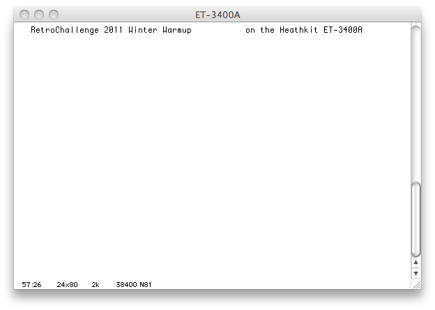
Which results in this on my mac:
I've been able to do some things with the HP 7475A plotter by hooking it up to the Mac and typing simple commands. I'll be working on getting the ET-3400A speaking its language tomorrow. Here's a pic of it along with my other trusty lab tech.
The ET-3400A is now driving the HP 7475A Plotter! I wanted to show a nice simple picture and little bit of text, but not too much so that it wouldn't take too long to plot. I chose a nice design from Paleoferrosaurus's 2011 Winter Warmup . (I'll try to keep these links updated as Paleoferrosaurus reorgs his site after the challenge.)
The ET-3400A doesn't have any BASIC, sine, cosine, or even floating point capability. I certainly wasn't going to be able to obtain or write fp and trigonometric functions before the end of the challenge. However, I do have a pretty smart macro assembler that can do floating point and trig functions. Using looping macros and these functions, I was able to get the assembler to generate a long table of vertices. The structure of that part of the program follows Paleoferrosaurus's BASIC program structure. In the list of vertices, I place a special code to lift the pen at the appropriate times. The section of the program running through the list looks for this code and does the right thing.
The HP 7475A plotter takes a series of 2-letter commands followed by numeric parameters. These are things like "PA1,1;" to move the pen, "PD;" to put the pen down on the paper, and "PA1,255;" to drag the pen to a new position. The units of the plotter are tiny, .00098 of an inch. However, it has built-in scaling. Since I wanted to work with single byte integers, I set up an area on the page so that 0,0 is in the lower left corner and 255,255 is the upper right. The table of generated vertices has x and y values from 1 to 255, with (128,128) being the center of the area.
Although my 6800 is pretty slow, the plotter is even slower. The ET-3400A can send data to the plotter faster than it can digest it and plot. I used the plotter's DTR (data terminal ready) signal to determine when it was ready to receive more data. This DTR line is fed into the CTS line on the 6850 ACIA, and its status is checked before each byte is sent.
Here's the assembly program. It's long and boring, but if you scroll to the bottom you can see the bit of paleoferrosaurus's code. I provided the raw assembly here instead of the output listing file because that file is pretty big. The listing gets big because the looping macros are all unrolled. However, it's cool to look at how the vertices are generated, so you can see the listing here.
plot.asm:
	PAGE	0

sercsr	equ	$2000
serdata	equ	$2001
lcdctl	equ	$2400
lcddata	equ	$2401

redis	equ	$fcbc
outbyt	equ	$fe20

	org	$2800

main:
	jsr	lcd_init
	jsr	ser_init
	jsr	plotter_init

	ldx	#paleoferrosaurus_plot
	jsr	plotter_doplot

	ldx	#message
	jsr	ser_putstring

	jsr	plotter_putpenaway

mainloop:
	jsr	ser_getchar
	jsr	redis
	jsr	outbyt
	cmpa	#$08
	beq	backspace
	jsr	lcd_putchar
	jsr	ser_putchar
	bra	mainloop
backspace:
	ldaa	#$10
	jsr	lcdsendctl
	bra	mainloop

; LCD routines

lcd_init:
	ldaa	#$38		; 8bit interface, 2-line display, 5x7 chars
	bsr	lcdsendctl
	ldaa	#$1		; clear display
	bsr	lcdsendctl
	ldaa	#$0e		; display on, cursor on, blink off
	bsr	lcdsendctl
	rts

lcd_putchar:
	psha
senddlp:
	ldaa	lcdctl
	anda	#$80
	bne	senddlp
	pula
	staa	lcddata
	rts

lcd_string:
	psha
display_lp:
	ldaa	0,x
	beq	display_done
	bsr	lcd_putchar
	inx
	bra	display_lp
display_done:
	pula
	rts

lcdsendctl:
	psha
sendclp:
	ldaa	lcdctl
	anda	#$80
	bne	sendclp
	pula
	staa	lcdctl
	rts

; Plotter routines

plotter_init:
	ldx	#plotter_init_string
	jsr	ser_putstring
	clr	plotter_penstate
	rts

plotter_plot_absolute:
	ldx	#plotter_plot_absolute_string
	jsr	ser_putstring
	rts

plotter_penup:
	ldx	#plotter_penup_string
	jsr	ser_putstring
	clr	plotter_penstate
	rts

plotter_pendown:
	ldx	#plotter_pendown_string
	jsr	ser_putstring
	clr	plotter_penstate
	inc	plotter_penstate
	rts

plotter_putpenaway:
	ldx	#plotter_penaway_string
	jsr	ser_putstring
	clr	plotter_penstate
	rts

plotter_doplot:
	stx	plotter_savex
	bsr	plotter_penup
	ldx	plotter_savex

plotter_doplot_lp:
	ldaa	0,x		; get next x coord
	beq	plotter_special	; check for special case
	inx

	stx	plotter_savex
	bsr	plotter_plot_absolute
	ldx	plotter_savex

	jsr	printa
	ldaa	#','
	jsr	ser_putchar
	ldaa	0,x		; get next y coord
	inx
	jsr	printa
	ldaa	#';'
	jsr	ser_putchar

	ldaa	plotter_penstate
	bne	plotter_doplot_lp

	stx	plotter_savex
	bsr	plotter_pendown
	ldx	plotter_savex

	bra	plotter_doplot_lp

plotter_special:
	ldab	1,x
	beq	plotter_doplot_done
	inx
	inx
	stx	plotter_savex
	bsr	plotter_penup
	ldx	plotter_savex

	bra	plotter_doplot_lp

plotter_doplot_done:
	rts

printa:				; quick-n-dirty routine to print A as decimal ascii
	pshb
	tab
	clra

printa_0:
	cmpb	#100
	blo	printa_1
	subb	#100
	inca
	bra	printa_0
printa_1:
	adda	#'0'
	jsr	ser_putchar
	clra
printa_2:
	cmpb	#10
	blo	printa_3
	subb	#10
	inca
	bra	printa_2
printa_3:
	adda	#'0'
	jsr	ser_putchar
	tba
	adda	#'0'
	jsr	ser_putchar

	pulb
	rts

; Serial port routines

ser_init:
	psha
	ldaa	#3		; ACIA master reset
	staa	sercsr
	ldaa	#$56		; rxint off, rts- high, txint off, 8N1, div by 64
	staa	sercsr
	pula
	rts

ser_getchar:
	ldaa	sercsr		; retrieve status register
	anda	#$01		; check for character received
	beq	ser_getchar
	ldaa	serdata		; read received character
	rts

ser_putstring:
	psha
send_lp:
	ldaa	0,x
	beq	send_done
	bsr	ser_putchar
	inx
	bra	send_lp
send_done:
	pula
	rts

ser_putchar:
send_via_rts:
	staa	savea
	stab	saveb
	stx	savex

ser_putchar_wait:
	ldab	sercsr		; wait for serial device to assert CTS
	andb	#8
	bne	ser_putchar_wait

	ldx	#bitbuf+1	; put bits into bitbuf

	ldab	#8		; send 8 databits from A, lsb first
	stab	bitcnt

bitlp1:
	lsra			; grab the lowest bit out of A
	rorb			; move bit into correct position in b
	lsrb
	andb	#$40		; isolate bit
	orab	#$16		; OR in rest of required serial status register
	stab	0,x		; save in bitbuf
	inx

	dec	bitcnt
	bne	bitlp1

	ldx	#bitbuf		; take prepped bits from bitbuf
	ldab	#10		; send 10 bits
bitlp2:
	ldaa	0,x
	inx
	staa	sercsr		; set RTS signal

txbaud	equ	9600

	if	txbaud=38400

	nop			; 3 nops (6 cycles) gives 38400 baud
	nop
	nop

	elseif	txbaud=9600
				; or waste 80 cycles for 9600 baud
	ldaa	#13		; (2 cycles)
bitlp3:
	deca			; (2 cycles)
	bne	bitlp3		; (4 cycles)

	elseif

	error	we don't do that txbaud yet

	endif

	decb
	bne	bitlp2

	ldaa	savea
	ldab	saveb
	ldx	savex
	rts

; Constants, variables, and lists go here

; temp variables for ser_putchar
savea:	fcb	0
saveb:	fcb	0
savex:	fdb	0
bitcnt:	fcb	0
bitbuf:	fcb	$16		; start bit (0)
	fcb	0,0,0,0,0,0,0,0	; 8 data bits
	fcb	$56		; stop bit (1)

plotter_init_string:
		; init plotter, set scaling points, set scale factor,
		; select pen #1
	fcb	"IN;IP2200,1000,8200,7000;SC0,255,0,255;SP1;",0

plotter_penaway_string:
	fcb	"SP0;",0

plotter_plot_absolute_string;
	fcb	"PA",0

plotter_penup_string;
	fcb	"PU;",0

plotter_pendown_string;
	fcb	"PD;",0

plotter_penstate:
	fcb	0
plotter_savex:
	fdb	0

message:
	fcb	"SP2;SR1.5,3.0;"
	fcb	"PA-35,280;"
	fcb	"LB","RetroChallenge 2011 Winter Warmup on the Heathkit ET-3400A",3
	fcb	"PA15,260"
	fcb	"LB","plotting to the HP 7475A on Jan 31, 2011",3
	fcb	0

paleoferrosaurus_plot:

; 100  HGR2
; 110  HCOLOR= 3
; 130  LET R1 = 90
; 140  LET R9 = (22 / 7) / 180
; 150  REM  DRAW A BOX
; 160  HPLOT 0,0 TO 279,0
; 170  HPLOT 279,0 TO 279,191
; 180  HPLOT 279,191 TO 0,191
; 190  HPLOT 0,191 TO 0,0
; 275  FOR T = 0 TO 135 STEP 45
; 300  LET RX = 10:RY = 90: GOSUB 2000
; 320  NEXT T
; 330  PRINT "ALL DONE!"
; 999  END
; 2000  REM  DRAW A DASHED ELLIPSE
; 2001  LET F = 0
; 2010  REM
; 2020  FOR I = 0 TO 360 STEP 10
; 2040  LET X2 = RX *  COS (I * R9)
; 2050  LET Y2 = RY *  SIN (I * R9)
; 2060 X9 = X2 *  COS (T * R9) + Y2 *  SIN (T * R9)
; 2070 Y9 = Y2 *  COS (T * R9) - X2 *  SIN (T * R9)
; 2071  IF F1 = 0 THEN 2080
; 2072  HPLOT X5,Y5 TO 140 + X9,96 + Y9
; 2073  GOTO 2081
; 2080  HPLOT 140 + X9,96 + Y9
; 2081 F1 = 255
; 2082  LET X5 = 140 + X9
; 2083  LET Y5 = 96 + Y9
; 2090  NEXT I
; 2100  RETURN

r9	set	CONSTPI / 180.0		; radians per degree
maxr	set	127
rx	set	maxr * 0.1		; ellipse length w/ x scale factor
ry	set	maxr * 0.9		; ellipse length w/ y scale factor
cx	set	128			; center x,y
cy	set	128
					; draw a box
	fcb	cx-maxr,cy-maxr		;  lower-left
	fcb	cx+maxr,cy-maxr		;  to lower-right
	fcb	cx+maxr,cy+maxr		;  to upper-right
	fcb	cx-maxr,cy+maxr		;  to upper-left
	fcb	cx-maxr,cy-maxr		;  and back to lower-left
	fcb	0,1

t	set	0			; for t=0 to 135 step 45
	rept	4

f	set	0			; f=0

i	set	0			; for i=0 to 360 step 10
	rept	37

x2	set	rx * cos (i * r9)		; calc x on ellipse
y2	set	ry * sin (i * r9)		; calc y on ellipse
x9	set	x2 * cos (t * r9) + y2 * sin (t * r9)	; rotate x2,y2 by t
y9	set	y2 * cos (t * r9) - x2 * sin (t * r9)	; to give x9,y9

	fcb	int(cx + x9), int(cy + y9)

i	set	i+10
	endm
	fcb	0,1			; x=0,y=1 in the stream indicates pen-up

t	set	t+45
	endm

	fcb	0,0			; x=0,y=0 in the stream indicates done
The loops use "rept" instead of "while" because there's a bug in the assembler and it wasn't ending the loops properly.
Here's the movie of it all in action:
And here's a scan of the page it produced:

Thank you, paleoferrosaurus, for the nice drawing.
Today is the last day of the challenge. I had a blast and now I'm a bit sad that it's come to the end. I'll probably play with the ET-3400 and ET-3400A trainers a bit more, but as with all these projects, it's difficult to make the time to spend on them "now" when there's always "later".
I'll probably focus on gathering all the individual parts (ICs, resistors, capacitors, etc.) from the EE-3401 and EE-3402 instructional courses and restoring them back into complete kits. There's also some scanning to do to get the second of these courses online. Plus the first course has an audiotape and flipchart piece. A friend of mine converted the audiotape to CD last spring, so that's preserved, but the flipchart needs to be scanned now. Finally, I've got to find a good storage container for these trainers so they don't get so dusty again!
Until next time!
Gilbert
Gilbert Coville